Onkyo DVS 353 Service Manual

This is the 26 pages manual for Onkyo DVS 353 Service Manual.
Read or download the pdf for free. If you want to contribute, please upload pdfs to audioservicemanuals.wetransfer.com.

Page: 1 / 26
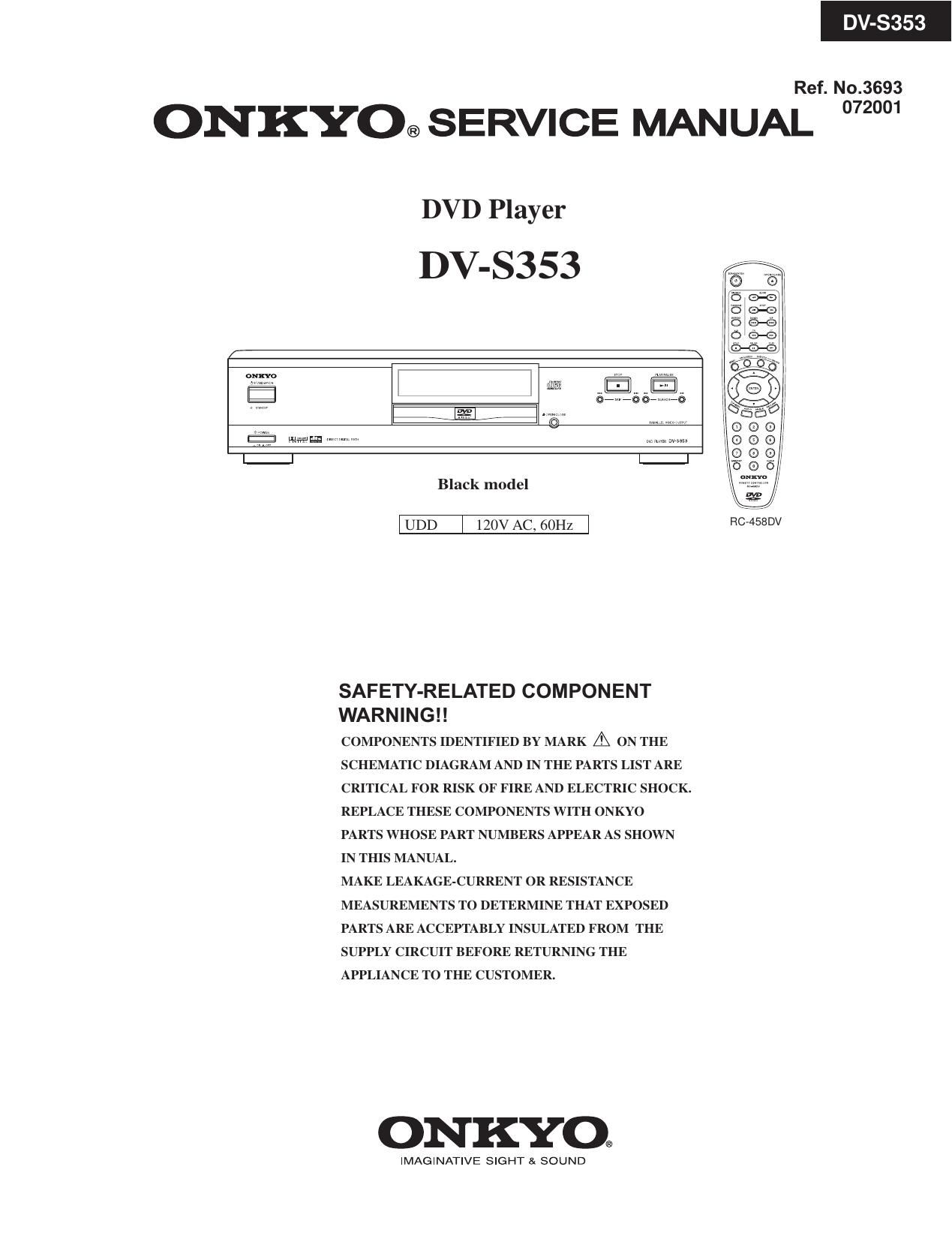
Onkyo DVS 353 Service Manual

Extracted text from Onkyo DVS 353 Service Manual (Ocr-read)


Page 1

DV-S353 Specifications and features are subject to change without notice. DVD Player Power supply AC 120 V, 60 Hz Power consumption 16 W Weight 8.2 lbs External dimensions 17 1/8" x 3 7/8" x 12 11/16" (W/H/D) Signal system NTSC Frequency range (digital audio) DVD linear sound: 48 kHz sampling 4 Hz to 22 kHz 96 kHz sampling 4 Hz to 44 kHz Signal-to-noise ratio (digital audio) More than 95 dB Audio dynamic range (digital audio) More than 95 dB Harmonic distortion (digital audio) Less than 0.005 % Wow and flutter Below measurable level Operating conditions Temperature: 5˚C to 35˚C (41˚F to 95˚F), Operation status: Horizontal Outputs Video output 1.0 V (p-p), 75 ohm , negative sync., pin jack 1 S-video output (Y) 1.0 V (p-p), 75ohm , negative sync., Mini DIN 4-pin 1 (C) 0.286 V (p-p), 75ohm Component video output (Y) 1.0 V (p-p), 75ohm , negative sync., pin jack 1 (P B)/(P R) 0.7 V (p-p), 75ohm pin jack 2 Audio output (digital output Optical) Optical connecter 1 Audio output (digital output Coaxial) 0.5 V (p-p), 75ohm , pin jack 1 Audio output (2-Channel Audio) 2.0 V (rms), 320ohm , pin jack (L, R) 1 Supplied Accessories Audio/video connection cable 1 Remote controller (RC-458DV) 1 Batteries (size AAA/R3) 2 SPECIFICATION

Page 2

DV-S353 SERVICE NOTES WARNING WARNING:TO REDUCE THE RISK OF FIRE OR ELECTRIC SHOCK, DO NOT EXPOSE THIS APPLIANCE TO RAIN OR MOISTURE. CAUTION:TO REDUCE THE RISK OF ELECTRIC SHOCK, DO NOT REMOVE COVER (OR BACK). NO USER-SERVICEABLE PARTS INSIDE. REFER SERVICING TO QUALIFIED SERVICE PERSONNEL. The lightning flash with arrowhead symbol, within an equilateral triangle, is intended to alert the user to the presence of uninsulated ìdangerous voltageî within the productís enclosure that may be of sufficient magnitude to constitute a risk of electric shock to persons. The exclamation point within an equilateral triangle is intended to alert the user to the presence of important operating and maintenance (servicing) instructions in the literature accompanying the appliance. WARNINGRISK OF ELECTRIC SHOCK DO NOT OPEN RISQUE DE CHOC ELECTRIQUE NE PAS OUVRIR AVIS This unit contains a semiconductor laser system and is classified as a CLASS 1 LASER PRODUCT. So, to use this model properly, read this Instruction Manual carefully. In case of any trouble, please contact the store where you purchased the unit. To prevent being exposed to the laser beam, do not try to open the enclosure. CAUTION: VISIBLE LASER RADIATION WHEN OPEN AND INTERLOCK FAILED OR DEFEATED. DO NOT STARE INTO BEAM. CAUTION: THIS PRODUCT UTILIZES A LASER. USE OF CONTROLS OR ADJUSTMENTS OR PERFORMANCE OF PROCEDURES OTHER THAN THOSE SPECIFIED HEREIN MAY RESULT IN HAZARDOUS RADIATION EXPOSURE. The label on the right is applied on the rear panel except for USA and Canadian models. 1. This unit is a CLASS 1 LASER PRODUCT and employs a laser inside the cabinet. 2. To prevent the laser from being exposed, do not remove the cover. Refer servicing to qualified personnel. CLASS 1 LASER PRODUCT LASER CAUTION LASER DIODE Never look at the laser light beam through the objective lens. The visible laser beam may harm the human eye. Use an appropriate viewer or TV camera to observe the laser beam. Any laser diode will be damaged by a large current or pulse. Avoid current surges and electrostatic discharges. Safety grounding of the human body and all measuring equipment, jigs and tools is absolutely necessary. The use of a grounding mat on the workbench and floor is necessary. Even a small electrostatic discharge from the human body may destroy the laser diode instantaneously or reduce its life time. The pins of the laser diode may be shorted at the factory by a solder bridge at the FPC for protection during transportation and storage of the unit. If this is the case, open the short circuit (accessible from the bottom side of the module) quickly with grounded soldering iron (less than 300C) . The damage of the diode might be indicated by an increase of the laser current.

Page 6

DV-S353 SCHEMATIC DIAGRAM To power supply PC board Standby LED PC board Search backward Search forward RED Skip backward Skip forwardPLAY/PAUSE STOP OPEN/CLOSE IC901 IC-CXP82324 From Power supply PC board Front circuit PC board FL tube FL901 To main circuit PC board Power switch PC board

Page 21

DV-S353 PACKING VIEW/ PARTS LIST Front Rear Right side Front DV-S353(B) Accessory REF. NO. PART NO. DESCRIPTION REF. NO. PART NO. DESCRIPTION 5 J96000041000 Carton box 12 20194780XX Cable tie 6 J97200046010 Pad R 14 J94310007000 1P 01000, Pin cord 7 J97200046020 Pad L 15 J90300022000 Warrany card 8 J94330001000 3P1500, Audio connection cable J90400048000 POS label 17 55167260XX Remote controller RC-458DV with poly cover 10 J97000501010 Poly bag, Power cord 18 3010054 Battery UM3 with poly cover 20 J90200021000 Instruction manual 11 J97000002000 Poly bag16 with poly cover 20 15 18 17 7 6 8 Tape Rear Front5 5 16 21 29110141 PP tape 21 22 29100097-1A Poly bag 350 x 250 29100037-1A Poly bag 650 x 500 23 23 (Poly bag)

Page 24

PIN NUMBER DESCRIPTIO N PIN NAME MAIN FUNCTIO N TYPE 117 EMI Interface CPU_OE OUTPUT_ENABLE I/O 118 EMI Interface CPU_RAM_CLK SDRAM CLOCK O 119 - VDD2_5 2.5V POWER SUPPLY POWER 120 CLOCK & RESET PIX_CLK 27 MHz main clock I 121 - VSS GROUND POWER 122 CLOCK & RESET VDD_PLL VDD PLL=2.5V POWER 2.5V 123 CLOCK & RESET VSS_PLL GND PLL=GND POWER GND 124 CLOCK & RESET RESET CHIP RESET I 125 INTERRUPT IR Q2[2] IRQ[2](MD_IR Q) I 126 INTERRUPT IR Q2[1] IRQ[1](ATAPI IR Q) I 127 INTERRUPT IR Q2[0] IRQ[0](SERVO_IR Q) I 128 EMI Interface CPU_BE [0] BYTE0 ENABLE O 129 EMI Interface CPU_BE [1] BYTE1 ENABLE O 130 EMI Interface CPU_RW READ-NOT WRITE O 131 EMI Interface CPU_WATE WATE STATE I 132 EMI Interface CPU_CE [4] CHIP SEL.BANK3 O 133 EMI Interface CPU_CE [3] CHIP SEL.BANK2 O 134 EMI Interface CPU_CE [2] CHIP SEL.BANK1 O 135 EMI Interface CPU_CE [0] DARAM_RAS0 O 136 - VDD3_3 3.3V POWER SUPPLY POWER 137 - VSS GROUND POWER 138 EMI Interface CPU_RAS1 DARAM RAS I/O 139 EMI Interface CPU_CAS [0] DARM CAS0 O 140 EMI Interface CPU_CAS [1] DRAM O 141 EMI Interface CPU_DATA [0] DATA [0] I/O 142 EMI Interface CPU_DATA [1] DATA [1] I/O 143 EMI Interface CPU_DATA [2] DATA [2] I/O 144 EMI Interface CPU_DATA [3] DATA [3] I/O 145 EMI Interface CPU_DATA [4] DATA [4] I/O 146 EMI Interface CPU_DATA [5] DATA [5] I/O 147 EMI Interface CPU_DATA [6] DATA [6] I/O 148 EMI Interface CPU_DATA [7] DATA [7] I/O 149 - VDD2_5 2.5V POWER SUPPLY POWER 150 - VSS GROUND POWER 151 EMI Interface CPU_DATA [8] DATA [8] I/O 152 EMI Interface CPU_DATA [9] DATA [9] I/O 153 EMI Interface CPU_DATA [10] DATA [10] I/O 154 EMI Interface CPU_DATA [11] DATA [11] I/O 155 EMI Interface CPU_DATA [12] DATA [12] I/O 156 EMI Interface CPU_DATA [13] DATA [13] I/O 157 EMI Interface CPU_DATA [14] DATA [14] I/O 158 EMI Interface CPU_DATA [15] DATA [15] I/O 159 - VDD3_3 3.3V POWER SUPPLY POWER 160 - VSS GROUND POWER 161 EMI Interface CPU_ADR [1] ADR [1] O 162 EMI Interface CPU_ADR [2] ADR [2] O 163 EMI Interface CPU_ADR [3] ADR [3] O 164 EMI Interface CPU_ADR [4] ADR [4] O 165 EMI Interface CPU_ADR [5] ADR [5] O 166 EMI Interface CPU_ADR [6] ADR [6] O 167 EMI Interface CPU_ADR [7] ADR [7] O 168 EMI Interface CPU_ADR [8] ADR [8] O 169 EMI Interface CPU_ADR [9] ADR [9] O 170 EMI Interface CPU_ADR [10] ADR [10] O 171 - VDD2_5 2.5V POWER SUPPLY POWER 172 - VSS GROUND POWER 173 EMI Interface CPU_ADR [11] ADR [11] O 174 EMI Interface CPU_ADR[12] ADR[12] O