Onkyo DVC 501 Service Manual

This is the 33 pages manual for Onkyo DVC 501 Service Manual.
Read or download the pdf for free. If you want to contribute, please upload pdfs to audioservicemanuals.wetransfer.com.

Page: 1 / 33
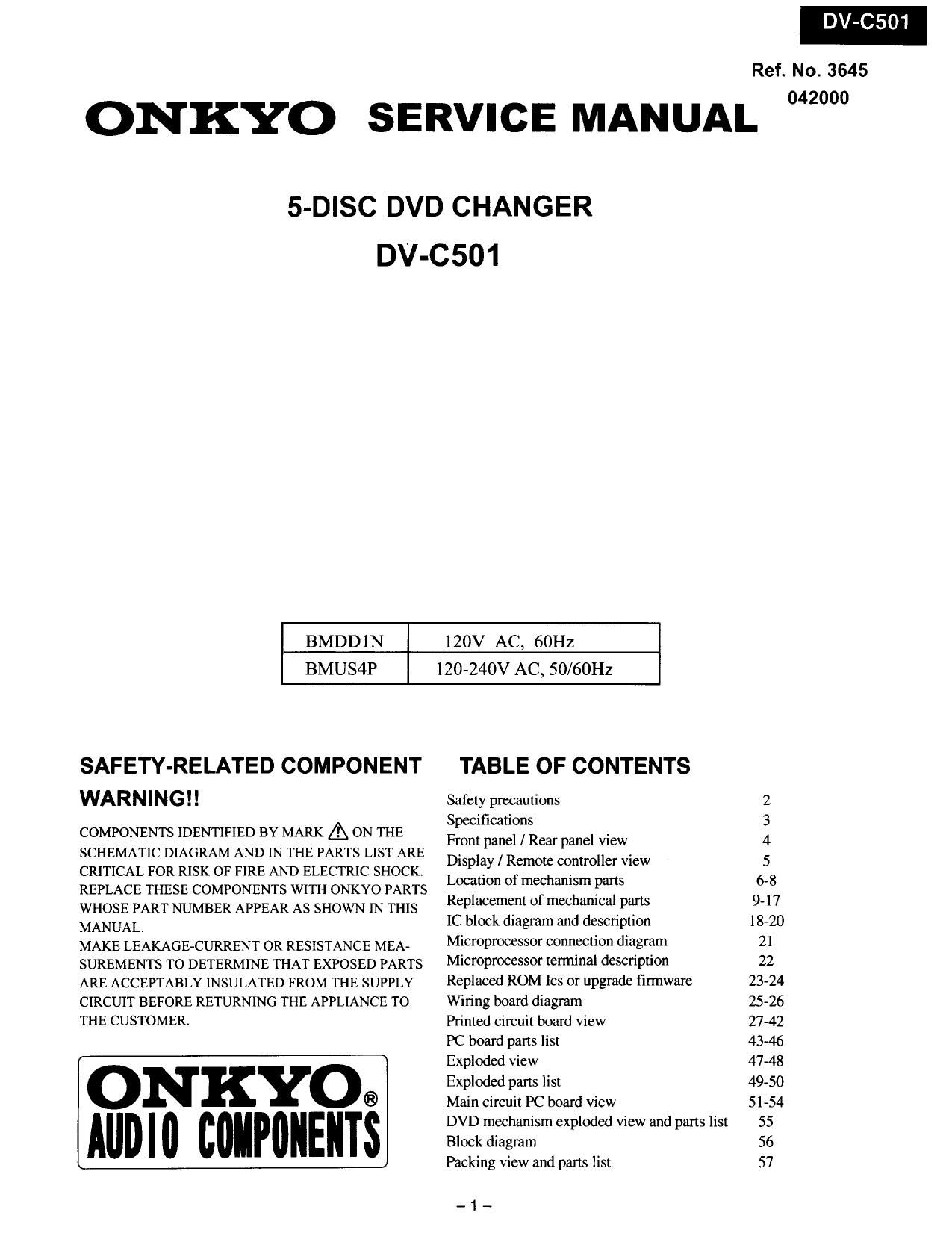
Onkyo DVC 501 Service Manual

Extracted text from Onkyo DVC 501 Service Manual (Ocr-read)


Page 1

Refi

ONKYO SERVICE MANUAL

5-DISC DVD CHANGER
DV-C 501

BMDD 1 N

120V AC, 60Hz

BMUS4P

120-24OV AC, 50/60Hz

SAFETY-RELATED COMPONENT
WARNINGII

COMPONENTS IDENTIFIED BY MARK A ON THE
SCHEMATIC DIAGRAM AND IN THE PARTS LIST ARE
CRITICAL FOR RISK OF FIRE AND ELECTRIC SHOCK.
REPLACE THESE COMPONENTS WITH ONKYO PARTS
WHOSE PART NUMBER APPEAR AS SHOWN IN THIS
MANUAL

MAKE LEAKAGE~CURRENT OR RESISTANCE MEA-
SUREMENTS TO DETERMINE THAT EXPOSED PARTS
ARE ACCEPTABLY INSULATED FROM THE SUPPLY
CIRCUIT BEFORE RETURNING THE APPLIANCE TO
THE CUSTOMER.

ON KYO®
AUDIO COIIPIIIEIIIS

TABLE OF CONTENTS

Safety precautions

Specifications

Front panel / Rear panel view

Display / Remote controller View
Location of mechanism parts
Replacement of mechanical parts

IC block diagram and description
Microprocessor connection diagram
Microprocessor terminal description
Replaced ROM Ics or upgrade firmware
Wiring board diagram

Printed circuit board View

PC board parts list

Exploded view

Exploded parts list

Main circuit PC board view

DVD mechanism exploded View and pans Iisl
Block diagram

Packing view and parts list

_1_

MAWN

9- l 7
18-20
21
22
2344
25-26
27-42
43-46
47-48
49-50
51-54
55
56
57

No. 3645
042000

Page 2

SAFETY PRECAUTIONS

WARNING
Ad
Els-

lARIIING' T0 REIIIltDIcI THE T.RISK 0F
ELECTRIC SIM, REIJVE
GOVER(0R BACK). II) USERSERVICEAEE
PART INSIM, REFER SERVIGIIII T0
IIIALIFIED SERVICE PERMEL.

within the product's endows that may be of sufficient magmuda Io conslilLte

The lightning flash with arrowhead symbol, wih'n an equilateral triange, is
: : iflended to alert the user to the presence of tn'nstlaed uangerous valage'
a risk of electric shock to persons.


' The melamalion point VIlIhIn an oquilatetal lriange is irleudad Io alert Ire user
. to Ihe presence of inparlanl operating and mainenance (serviu'ng) inslruclion
ii the literature accorrpaming the appliance.
WARNNG: TO REDUCE THE RISK OF FIRE 0R ELECTRIC SHOCK DO NOT EXPOSE THIS APPLIANCETO RAN

OR MOISTURE. DANGEROUS HIGH VOLTAOES ARE PREfiN'I' NSDETHE ENCLOSURE. DO NOT OPENTHE
CABINET REFER SERVICINGTO QUALIFED PERSONIEL ONLY.

CAUTION : TO PREVENT ELECTRIC WCK, HATCH WDE BLADE OF PLUG TOWE SLOT, FULLY NSERT.

ATTENTION : POUR EVITER LES CHOCS ELECTRIGUE, INTRODLIRE LA LAME LA PLUB LARGE DA LA FIG-IE DNS Ll
HORNE CORRESPONDANTE DA LA PRJSE ET POWER NSQU' AU FOMDA

PRECAUTIONS

Replacing the fuses
For continued protection against risk fire replace only
with same type and same rating fuse

CIRCUIT No. P ART No. DESCRIPTION
F901 252157 1.25A-UL1'I -237

E This symbol located near the fuse indicates that the fuse
used is fast operating type. For continued protection against fire
hazard, replace with same type fuse. For fuse rating refer to the
marking adjacent to the symbol.

-I:]- Ce symbole indique que le fusible utlise est a rapide.
Pour unc protection permanente. n'utiliser que dcs fusibles de meme
type. Ce darmier est indiquc la qu 1e prescnt symbol est appose.

LASER BEAN CAUTION LABEL

when the power supply is being tur- ned on, you may not remove
this laser cautions Iabel, rodintian of a Ilse: my be r eceivcd.

Pickup Head consists of a laser diode that very susceptihk to enter ml
static electricity.

Although it operas pr operly after replacement, if it Wu mhject to
electrostatic dischlrge during 1' epheement, its if: might be slmnened.
When replacing, use a conductiv e mat, solderingiron with ground wire,
etc. to protect the Inner diode Ir um damage by static electriuty.

"" H'm"""" R' And also, the [SI and IC are some in above.