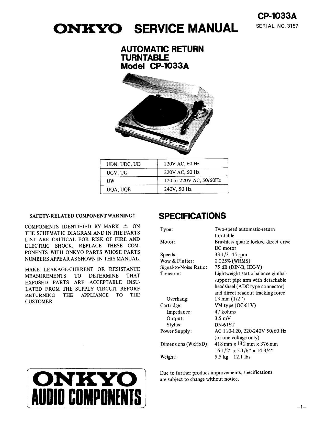
Onkyo CP 1033 A Service Manual
This is the 8 pages manual for Onkyo CP 1033 A Service Manual.
Read or download the pdf for free. If you want to contribute, please upload pdfs to audioservicemanuals.wetransfer.com.
Extracted text from Onkyo CP 1033 A Service Manual (Ocr-read)
Page 1
ONKYO SERVICE MANUAL
AUTOMATIC RETURN
TURNTABLE
Model CP-1033A
CP-1033A
SERIAL NO. 3157
UDN, UDC, UD 120v AC, 60 Hz
UGV, UG 220v AC, 50 Hz
UW 120 or 220v AC, 50/60Hz
UQA, UQB 240v, 50 Hz
SAFETY-RELATED COMPONENT WARNINGM SPEC|F|CAT|0NS
COMPONENTS IDENTIFIED BY MARK A 0N T e, TWM eed automaticm
THE SCHEMATIC DIAGRAM AND IN THE PARTS y" turntagle m
LIST ARE CRITICAL FOR RISK OF FIRE AND . .
M t : B
ELECTRIC SHOCK. REPLACE THESE COM- 0 °' Drcuflljfzrquam mm due we
PONENTS WITH ONKYO PARTS WHOSE PARTS Speeds 334/3 45 rpm
NUMBERS APPEAR AS SHOWN IN THIS MANUAL. Wow & Flutter: 0.025%: (WRMS)
MAKE LEAKAGE-CURRENT OR RESISTANCE Signal-to-Noise Ratio: 75 dB (DIN-B, lEC-Y)
MEASUREMENTS TO DETERMINE THAT Tonearm: Lightweight Static Oalance gimbal~
EXPOSED PARTS ARE ACCEPTABLE lNSU- FPO" Pipe 3" With detaChable
LATED FROM THE SUPPLY CIRCUIT BEFORE headSheeMADCtypeconnemr)
RETURNING THE APPLIANCE TO THE and direct readout tracking force
CUSTOMER Ovexhang: 13 m (1/2)
Cartridge: VM type (QC-61V)
Impedance: 47 kohms
Output: 3.5 mV
Stylus: DN-6 1 ST
Power Supply: AC 110-120, 220-240v 50/60 Hz
(or one voltage only)
Dimensions (WxHxD): 418 mm x13 2 mm x 376mm
16-1/2" x 5-1/6" x 14-3/4"
Weight: 515 kg 12.1 lbs.
ON KYO
Alllllll BIIMPIINENIS
Due to further product improvements, specifications
are subject to change without notice.
Page 2
SERVICE PROCEDURES
Instruction resistance measurment
Connect the insulating-resistance tester between the plug
of power supply cord and chssis.
Specifications: G/W models 500 V more than 10 MD
Replacing the lamps
This unit used the lamps listed below.
Circuit No. Parts No. Description
PL201 210170 PL14V 0.06AW-2.0, Lamp
PL202 210170 PL14V 0.06AW-2.0, Lamp
Caution: Before replacing the lamps. Be sure to unplug
the power supply cable.
Connection diagram of motor assy
Before change
Motor me
Control Motor dig"?
pub CIYCLH!
pl: board
U-4
NAGD-1558a
Socket
P5
After change
From
Motor digital
CIICLIH
pc board
Socket
P5
ADJUSTMENT PROCEDURES
Automatic shut-off position adjustment
Adjust the shut-off position with the fine adjustment screw.
After the adjustment, apply lock-tite to the screw. To
adjust the shut-off position for earlier, turn the screw
counter-clockwise. To adjust the shut-off position for later,
turn the screw clockwise.
l. Stylus height adjustment (AUTO UP)
Set the tonearm in the up position and adjust the lifter
plate screw so the height of the stylus tip is 10mm
1' 3mm above the platter mat.
Gap (0.05 ~ 0.3 mm)
M icroswitch
Microswitch position
adjustment pin
Automatic
shut-off
position
adjustment Tongan-n
pin height
adjustment screw
(Manual up 11mm t 3mm)
2. Platter height adjustment
Return the unit to the upright position and rotate the
float base height adjustment screw. Adjust so that the
platter height is 13 mm 1 2 mm above the cabinet.
m. m"
mum.
rT-r1 w
(9 é/%K\\
@
n.- no.
mwmnmr