Onkyo CP 1027 F Service Manual

This is the 6 pages manual for Onkyo CP 1027 F Service Manual.
Read or download the pdf for free. If you want to contribute, please upload pdfs to audioservicemanuals.wetransfer.com.

Page: 1 / 6
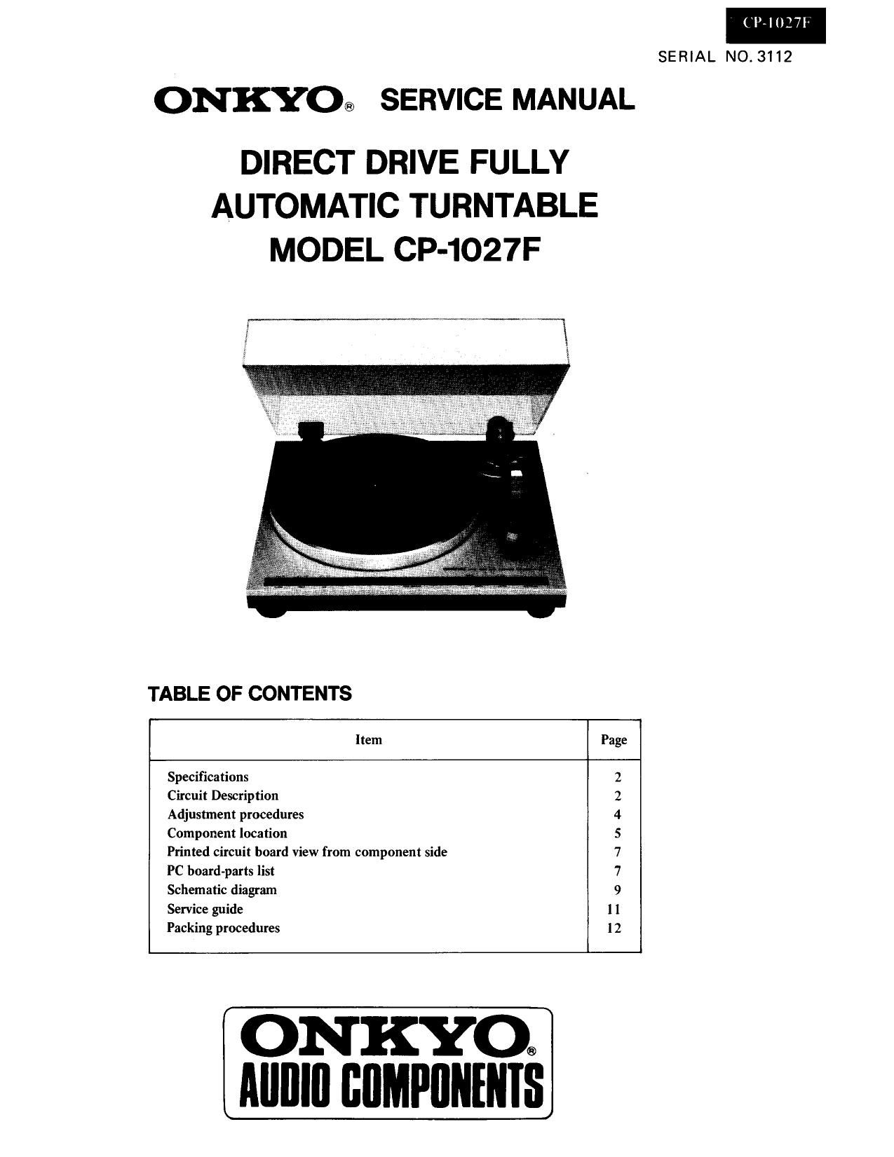
Onkyo CP 1027 F Service Manual

Extracted text from Onkyo CP 1027 F Service Manual (Ocr-read)


Page 2

('lrlUl?

ADJUSTMENT PROCEDURES

1. Lead-in Adjustment
Roughly adjust the pulley shutter so the stylus lowers
approximately into the lead-in grooves of a record. Next,
adjust the jumper circuit (1220 7 1225) on the printed
circuit board (NADG-1046).
Press the record size selector to 300m position and
confirm the lead-in position. When outside the lead-in
position, connect or cut the jumper wires by referring
to the below table.

Cut Connect

1225 inner outside
1220 03 mm
1221 0.6 mm
1222 1.2 mm
1223 2.4 mm
1224 4.8 mm

R703 VR'IK

r Return adjusting eccentric pin
, ,F'- ., . .i


Screw paint

Lead i __ ,

2. Auto-Return Adjustment
2-1 . Sensitivity Adjustment

*Remove the DD motor and arm motor connectors
and connect a millivoltmeter between the GND
and IN of the terminal of DG-AS (NADG-
1046).

*Move the tonearm to the innermost part of the
the record and, in a position such that the pulley
and deflection pin do not cover the end sensor
(D701, D702), turn R703 counterclockwise as
far as it will go and read the value on the milli-
voltmeter. (should be about lOOmV)

*Next, turn R703 clockwise to the point where the
millivoltmeter value has changed 2 - 3mV and set
R703 at that point.

Notes: 1.Do not cover the light of the outdoor
during adjustments.

2.1f parts on the printed circuit board of

RET-AS are replaced, perform the

sensitivity adjustment procedure de-

scribed above. No adjustments are

necessary when other parts are replaced.

2-2. Auto-retum position
Adjust the return position by the eccentric pin
attached by the tonearm base. To adjust the return
position for faster, turn the eccentric pin clockwise.
To adjust the return position for later, turn the
eccentric pin counterclockwise.

. Tonearm Height Adjustment

Turn the adjustment screw on top of the elevation
section clockwise to lower and counterclockwise to raise
the height of the tonearm during fully automatic opera-
tions.

specification 13 ~ 15mm

. Speed Adjustment

Set the speed control VR of the operation section to
about its mechanical center and, after confirming that
the green LED in the speed indicator window is illumi-
nated, adjust VR-45 and VR-33 on the main motor so
that a 3kHz test record is 3,000Hz at 45 rpm and
3,000Hz at 33 rpm.