Onkyo ASV 810 PRO Service Manual

This is the 35 pages manual for Onkyo ASV 810 PRO Service Manual.
Read or download the pdf for free. If you want to contribute, please upload pdfs to audioservicemanuals.wetransfer.com.

Page: 1 / 35
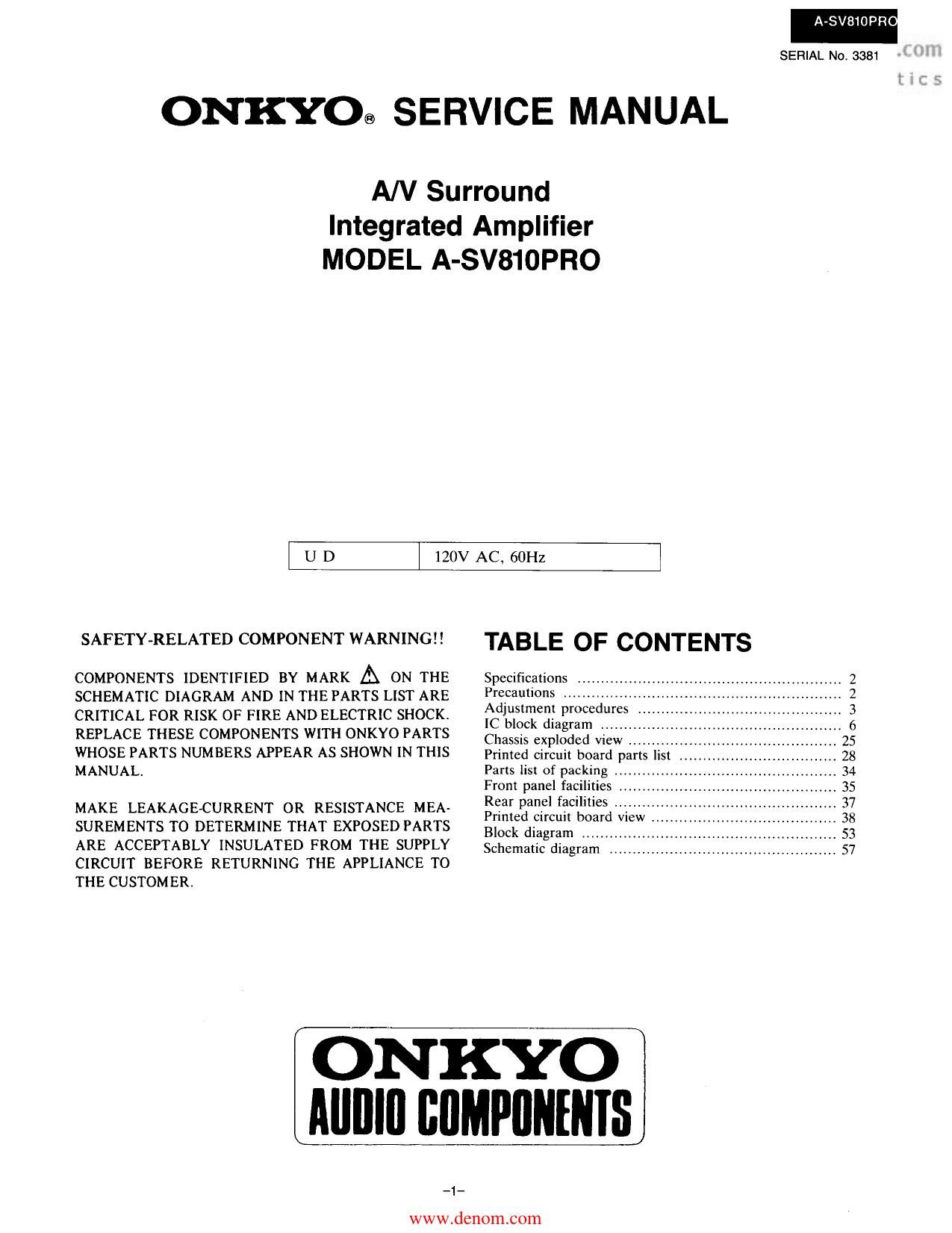
Onkyo ASV 810 PRO Service Manual

Extracted text from Onkyo ASV 810 PRO Service Manual (Ocr-read)


Page 1

A-SV81OPR O

SERIAL No, 3381

ONKYO® SERVICE MANUAL

A/V Surround
Integrated Amplifier
MODEL A-SV810PRO

UD

120V AC, 60H:

SAFETY-RELATED COMPONENT WARNINGII

COMPONENTS IDENTIFIED BY MARK A ON THE
SCHEMATIC DIAGRAM AND IN THE PARTS LIST ARE
CRITICAL FOR RISK OF FIRE AND ELECTRIC SHOCK.
REPLACE THESE COMPONENTS WITH ONKYO PARTS
WHOSE PARTS NUMBERS APPEAR AS SHOWN IN THIS
MANUAL.

MAKE LEAKAGE-CURRENT OR RESISTANCE MEA-
SUREMENTS TO DETERMINE THAT EXPOSED PARTS
ARE ACCEPTABLY INSULATED FROM THE SUPPLY
CIRCUIT BEFORE RETURNING THE APPLIANCE TO
THE CUSTOM ER.

TABLE OF CONTENTS

Specifications ..
Precautions .....
Adjustment procedures
IC block diagram
Chassis exploded v
Printed circuit board par 5 IS
Parts list of packing
Front panel facilities
Rear panel facilities
Printed circuit board View
Block diagram ........
Schematic diagram .,

ON KYO
Mllllll llllMPllllIlllS

_1_

www.dcn0m.c0m

Page 2

A-SV

PRO

SPECIFICATIONS

AMPLIFIER SECTION

Power Output:

Total Harmonic Distortion:

IM Distortion:

Damping Factor:

Sensitivity and Impedance:

Phono overload:

Frequency Response:

Phono RIAA Deviation:

Tone Control:

BY-PASS (two channel stereo) mode
75 watts per channel min. RMS. at 8 ohms, both
channels driven, from 20 Hz to 20,000 Hz, with
no more than 0.06 % total harmonic distortion.
DOLBY PRO-LOGIC mode
85 watts per channel min. HMS. at 8 ohms, front
L or R or C channel driven, 1,000 Hz with no more
than 0.5 % total harmonic distortion.
35 watts per channel min. RMS. at 8 ohms, rear
L and R channels driven, 1.000 Hz with no more
than 1 96 total harmonic distortion.
006 % at rated power
(BY- PASS mode)
0.06 96 at rated power
(BY- PASS mode)
90 at 8 ohms (FRONT)
PHONO: 5 mV/50 kohms
CD, TUNER, TAPE/DAT (PLAY),
VDP, 085 VIDEO 1-4 (PLAY):
300 mV/50 kuhms
TAPE/DAT, VIDEO1-3 (REC):
300 mV/2.2 kohrns
PREOUT/SUB WOOFER:
I V/SOO ohms
110 mV RMS. at1 kHz, 0.05 % THD.
2 to 100.000 Hz. +/-3 dB
(BY-PASS mode)
20 to 20,000 Hz, 4-1-08 dB

Signal to Noise Ratio

(BY- PASS mode):

BASS: *l-12 dB at 20 HI
MID: +/-12 dB at 850 Hz
TREBLE: +/-l 2 dB at 20 kHz
PHONO : 80 dB

(IHF A, 5 mV input)
CD. VDP: 105 dB (IHF A)

PRECAUTIONS

1. Replacing the fuses
For continued protection against risk fire, replace only with same type and same rating fuse.

CIRCUIT NO. PART NO. DESCRIPTION
F901 252052 7A ST-6, Primary fuse
F921, F922 252051 6A ST-6. Primary fuse

2. Insulation resistance measurement (Only U.S.A. model)

VIDEO SECTION
Sensitivity and

VDP, DBS, VIDEO 1-4 (PLAY) VIDEO input:

1 Vp-p, 75 ohms

VIDEO 1-3 (REC), MONITOR OUT VIDEO

1 Vp-p, 75 ohms

VDP, DBS, VIDEO 1, 2, 4 (PLAY) S-VIDEO

Y signal 1 Vp-p. 75 ohms
C signal 028 Vp-p, 75 ohms

VIDEO 1-2 (REC), MONITOR OUT S-VIDEO

Impedance:
output:
input:
output:
GENERAL

Power Supply:
Dimensions (W x H x D):

Weig ht:

Y signal 1 Vp-p. 75 ohms
C signal 0.28 Vp-p, 75 ohms

USA and Canadian model:
AC 120 V, 60 Hz
455 x 170 x 421 mm
17-15/16' x 6-11/16" x16-9/16'
17.5 kg., 38.6 lbs.

REMOTE CONTROL TRANSMITTER RC-IBSM

Transmitter:

Signal Range:

Power Supply:

Dimensions (W x H x D):

Weight:

Infrared

Approx. 5 meters (16 ft. 4")

Two AAA" batteries (1.5 V x 2)
67 x 30 x 200 mm

2-5/8 x 1-3/16' x 7-7/8
150 grams, 5.3 02.

(including batteries)

Specltications and features are subject to change without notice.

Connect the insulating~resistance tester between the plug of power supply cable and the terminal GND on the back panel.
Specifications; More than 10 M!) at 500V.

-2-
www.den0m.c0m

Page 8

A-SV810PRO

Pin No. Code Function Description

20 D7 A0 Output terminal for connection to the AO terminal of surround IC
YM7128.

21 D8 STBC Output terminal for connection to the STB terminal of electronic
variable resistor TC9213P-C.

22 D9 STBR Output terminal for connection to the STB terminal of electronic
variable resistor TC9213P-R.
Remote control VOL UP/DOWN control signal output terminals.

23 D10 VOL DOWN The VOL UP output is H" when the VOL UP code is input from

24 D11 VOL UP remote control. The VOL DOWN [S H when the VOL DOWN
code is input.

25 D12 D85 REC SELECTOR display (LED) output terminals,

26 DIS VDP The output corresponding to (eh current REC SELECTOR

27 D14 SOURCE position is H (lit).

28 015 STBY/ STAND~BY and RECEIVE display (LED) output terminal. H"

RECEIVE (lit continuously) during power off (standby) status.

When power is on, H" (lit) when codes from the remote control
are input for decoding.

29 R00 POWER Power supply (POWER) control output terminal. H" when power
is on.

30 R01 FILON Fluorescent display filament power supply output terminal.
H" when power is on (except during the rec standby status),

31 R02 Sa Segment output terminals.

32 R03 Sb H" when active.

33 R10 Sc

34 R11 Sd

35 R12 Se

36 R13 Sf

37 R20 Sg

38 R21 Sh

39 R22 Sj Segment output terminals.

40 R23 Sk H" when active.

41 R30 Sm

42 R31 Sn

43 R32 Sp

44 R33 Sr

45 R40 DIGA Digit output terminals.
Connected to expansion [Cs 74HC138 (2). which expand 4-bit data

46 R41 DIGB into 16

47 R42 DlGC Fluorescent grids 14H-IG are H" (active) corresponding to the
values of ill-EH in the 4-bit output data. A OH value of output

48 R43 DIGD to blank the display.

49 R50 EXP/7W Initial setting input terminal for switching the point of destination.
H: Export
J: Japan

50 R51 PROTECT Speaker protection detect input terminal.
When H. the speaker and headphone relays are off.

51 R52 SPON Speaker on detect input terminal.
When L, all speaker relays are off (FRONT R/L, CEN R/L.
and REAR R/L output are L").
H" during normal operation.

52 R53 - Not used. Connected to GND.

_8_
www.denom.com