Onkyo ASV 620 Service Manual

This is the 21 pages manual for Onkyo ASV 620 Service Manual.
Read or download the pdf for free. If you want to contribute, please upload pdfs to audioservicemanuals.wetransfer.com.

Page: 1 / 21
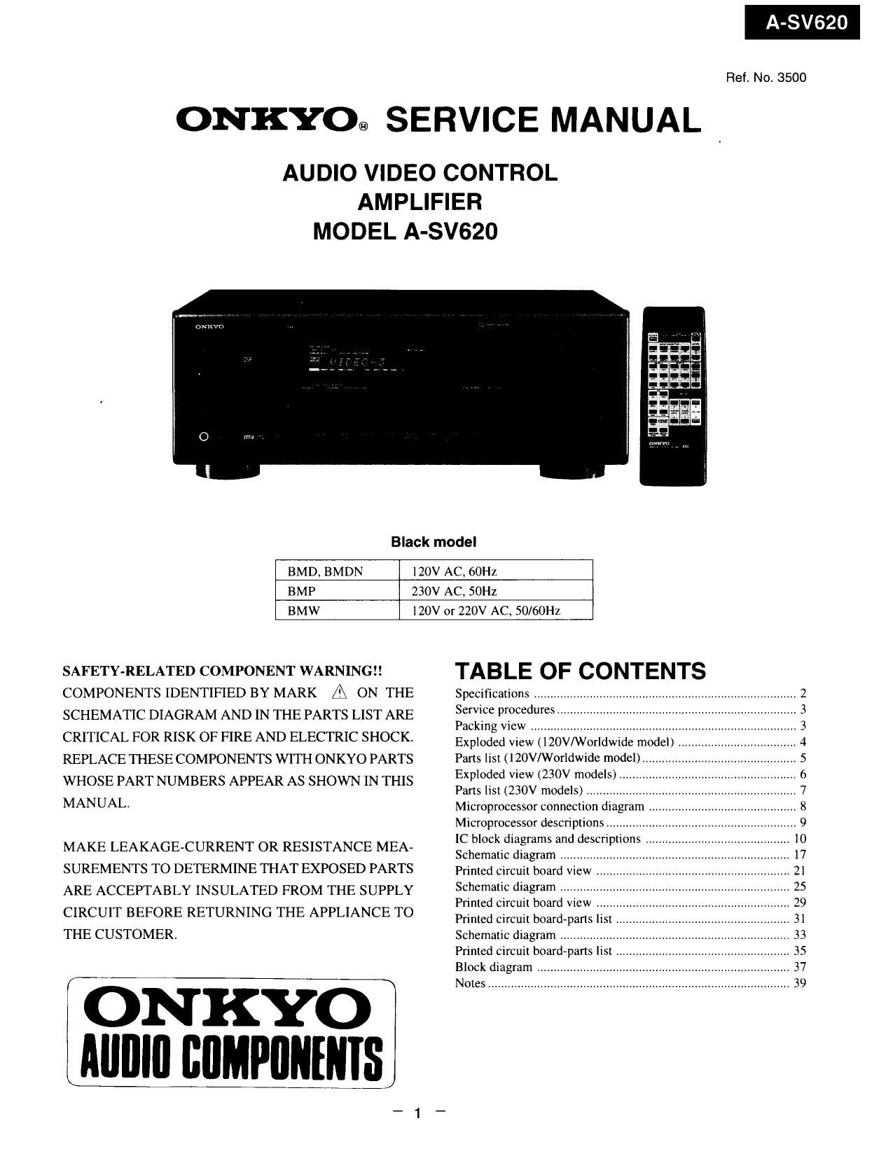
Onkyo ASV 620 Service Manual

Extracted text from Onkyo ASV 620 Service Manual (Ocr-read)


Page 1

Ref. No. 3500

ONKYO@ SERVICE MANUAL

AUDIO VIDEO CONTROL
AMPLIFIER
MODEL A-SV620

Black model

BMD, BMDN

120V AC, 60Hz

BMP 230V AC. SOHZ

BMW

120V or 220V AC, SO/GOI'IZ

SAFETY-RELATED COMPONENT WARNINGI!
COMPONENTS IDENTIFIED BY MARK fl ON THE
SCHEMATIC DIAGRAM AND IN THE PARTS LIST ARE
CRITICAL FOR RISK OF FIRE AND ELECTRIC SHOCK.
REPLACE THESE COMPONENTS WITH ONKYO PARTS
WHOSE PART NUMBERS APPEAR AS SHOWN IN THIS
MANUAL.

MAKE LEAKAGE-CURRENT OR RESISTANCE MEA-
SUREMENTS TO DETERMINE THAT EXPOSED PARTS
ARE ACCEPTABLY INSULATED FROM THE SUPPLY
CIRCUIT BEFORE RETURNING THE APPLIANCE TO
THE CUSTOMER

ONKYO
MIIIII] IIIIMPIIIIIIIIS

TABLE OF CONTENTS

Specifications .......
Service procedures
Packing View ..............................................
Exploded View (DOV/Worldwide model) ,
Parts list (HOV/Worldwide model)
Exploded view (230V models)
Parts list (230V models) ......
Microprocessor connection diagram ..
Microprocessor descriptions ...............
IC block diagrams and descriptions
Schematic diagram ..........
Primed circuit board view
Schematic diagram ..........
Printed circuit board view
Printed Circuit board-parts list i
Schematic diagram ..........
Printed circuit boardOparts list .
Block diagram ..
Notes .............

mqomzawwm

Page 2

A-SV620

SPECIFICATIONS

AMPLIFIER SECTION
Power Output

Front L/ honnels
120 watts per channel min. RMS. at 8
ohms, both channels driven, from 20 Hz
to 20.000 Hz, with no more than 038%
total harmonic distortion.

Continuous power output:
2 x 140 walls at 8 ohms {DIN}

Front LR and center channels
75W+75W+75W (1 kHz 0.08% Sohmsl
Rear channels (Rear only driven)
25 W + 25 W (I kHz 0.8 % 8 ohms)
Remote channels
75 W+75W(I kHz 0.| o/r Sohms)
lM Distortion: 0.08% at rated power (FRONT)
Dumping Factor' 60 at 8 ohms (FRONT)
Input sensitivities and impedance:
Phone: 25 mV/SO kohms
CD/Tuner/Tape playNideo in:
[50 mV/SO kohms

Output level and impedance:
Tape rec/Video out: [50 mV/2.2 kohms
Pre out (SUBWOOFER): I V/2.2 kohms

SERVICE PROCEDURES

1. Replacing the fuses

-._-_D- This symbol located near the fuse indicates that the
fuse used is fast operating type. For continued protection against
fire hazard, replace with same type fuse. For fuse rating refer to
the marking adjacent to the symbol.

fl Ce symbole indique que le fusible utlise est a rapide.
Pour une protection permanente, n'utiliser que des fusibles de
meme type, Ce darnier est indique la qu le present symbol est
appose.

CIRCUIT NO. PART NO. DESCRIPTION

F90] 252166Y 6.3A~UL/T-237. Primary
F902 252076 3.15A-TSC, Primary


F903 252075 2.5A-SE-EAK, Primary

NOTE: :120V model only

:230V model only
:Worldwide model only

2. To Initialize the unit
This device employs a microprocessor to perform various
functions and operations. If interference generated by an external
power supply, radio wave. or other electrical source results in
accident which causes the specified operations and functions to
operate abnormally.
To perform a result, please follow the procedure below.

Fhono Overload. IZU mV RMS at LOGO Hz. 0.5% THD

Frequency Response: 20 to 30000 Hz, +/-l dB

RIAA Deviation 20 to 20.000 Hz. #418 (3

Tone Control. BASS: +/-IO dB at IOO Hz
TREBLE: +/~lO dB at l0.00() Hz

Signal to Noise Ratio: PHONO: 80 dB (II-IF At 5 mV inpuil
CD/TAPE IOU dB (IHF A)

Muting: 7 0° dB

VIDEO SECTION

Signal sensinvny and

impedance: Input, output: I Vp-p. 75 ohms

GENERAL

Power Supply: USA & Canadian models

ACIZO V, 60 Hz

European models

AC230 V, 50 Hz

Worldwide models

120 and 220 V switchable. 50/60 HZ

Dimensions (W X H x D): 455 x I70 x 389 mm
l7VIS/I6" x 671 l/lé" X 1575/16"
Mass: 12,] kg (26.7 lbs)

Specifications and features are subject to change without notice.

1. Press and hold down the VIDEO-1 button, then press the
POWER button.

2. After clear" is displayed, the preset memory and each
mode stored in the memory, such as surround, are
initialized and will return to the factory settings.

Safety-check out

(Only U.S.A. model)

After correcting the original service problem, perform the
following safety check before releasing the set to the customer.
Connect the insulating-resistance tester between the plug of power
supply cord and the screw on the back panel.

Specifications: 33 MohmilO% at 500V.

. Change of voltage

Worldwide models are equipment with a voltage selector to
conform with local power supplies. This switch is located on the
back panel.

Be sure to set this switch to match the voltage of the power supply
in your area before turning the power switch on,

This switch is set to 220V at the factory. Voltage is changed by
sliding the groove in the switch with the screwdriver to the right
or left. Confirm that the switch has been moved all the way to the
right or left before turning the power switch on.

VOLTAGE
SELECTOR

220V~ 120V~