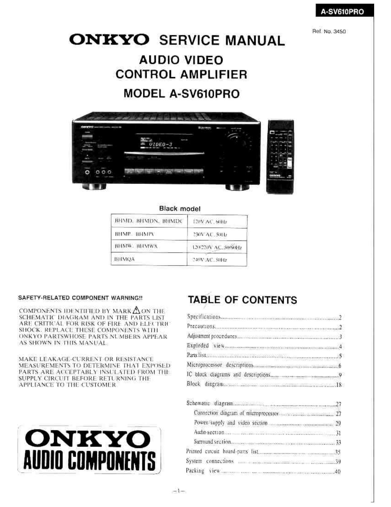
Onkyo ASV 610 Pro Service Manual
This is the 20 pages manual for Onkyo ASV 610 Pro Service Manual.
Read or download the pdf for free. If you want to contribute, please upload pdfs to audioservicemanuals.wetransfer.com.
Extracted text from Onkyo ASV 610 Pro Service Manual (Ocr-read)
Page 2
A-SV OPRO
SPECIFICATIONS
AMPLIFIER SECTION
Power Output:
Front UR channels
125 watts per channel min, HMS at 8 ohms.
both
channels driven, lrom 20 Hz to 20,000 Hz with
no more than 0.08% total harmonic distortion.
Dynamic power:
2 x 240 watts at 4 ohms
2 x 160 watts at 8 ohms
From L/R and center channels
70 watts per channel min. RMS at 8 ohms,
1 ,000 Hz, with no more than 0.08% total
harmonic distortion.
Ftear or Remote channels
20 watts per channel min. HMS. at 8 ohms
1.000 Hz. with no more than 0.8% tolal
harmonic dislonion.
Total Harmonic Dislorlion: 0.08% at rated power (FRONT)
lM Distortion: 0.08% at rated power (FRONT)
Damping Factor: 60 at 8 ohms (FRONT)
Sensitivity and impedance: Phono: 2.5 mV/So kohms
CD/Tape Play: 150 mV/SO kohms
Tape Rec: 150 mV/2.2 kohms
PRECAUTIONS
l. Replacing the fuses
For continued protection against risk of fire hazard.replace only
with same type and same rating fuse,
Circuit No, Pan No. Description
F90] 252l66Y 6.3A-UL/T-237, Primary {use
[7911,F912 252l66Y 6.3A-UL/r-237, Secondary fuse
>
F91 1,F)12 252079 6.3A-SE-EAK, Secondary fuse
NOTE: 2230V model only
2.Perfomt a reset
This device employs a microprocessor to perform various functions
and operations. if interfarence generated by an external power supp
radio waves, or other electrical source results in an accident which
causes the specified operations and functions to operate abnormally
To perform a reset, please follow the procedure below.
l.Press and hold down the CD button. then press the POWER butto
2."Test-" is displayed on the display for approximately 5 seconds.
3.While "Test-" is displayed. unplug the unit's power supply cord
4.Pres
3.Safety.check out
(Only U.S.A. model)
After correcting the original service problem perform the follwing
Connect the insulating-resistance tester between the plug of
1y,
II.
temory and parameters stores in memory, such as surround
Phono Overload:
Frequency Response
FllAA Deviation:
Signal to Noise Ratio
Muting:
VIDEO SECTION
120 mV HMS. at 1.000 Hz. 0.5% THD
20 to 20.000 Hz. +/-0.B dB
BASS: #710 dB at 100 HZ
-0: dB
Signal sensitivity and impedance
GENERAL
Dimensions {W x H x D):
Weight:
455 x 170 x 388 mm
Specifications and external appearance are subject to change wilhout
F902 252076 3.15AVSE-EAK, Primary fuse
F903 252075 2.5AVSEVEAK. AC outlet fuse
:240V model only
from its AC outlet, then "Testy" will disappear.
are initialized and will return to the factory settings.
safety Check before releasing the set to the customer.
power supply cord and terminal GND on the back panel.
Specifications: More than 10MB at 500V.
Tone Control'
20 to 30000 Hz, +/71 dB
TREBLE: #710 dB at 10,000 HZ
FHONO: 80 dB (IHF A. 5 mV Input)
CD/TAPE: 100 dB (IHF A)
VlDEO input, output: 1 Vp-p 75 ohms
17-15/16"x6»il/16"X1571/4"
135 kg (29.6 lbs)
notice because of product improvements.
Page 3
ADJUSTMENT PROCEDURES
l.ldlc Current Adjustment
1) Preparation
There should be no load and no signal, the volume knob
should be at the minimum position, and the speaker and
power switches should be off.
2) Turn the power switch to on.
3) Adjust the trim resistors R511.R512 and R546 so that :2: :2:
the voltage at the test points for the left,center and right
channels (P521,P522 and P551) is 1.2mV to 2.2mv. "Emmi"
ID mt
n
:2
4) Five mimutes later, readjust to 5 iOrSmV. m.
BY...
2. Checking the Operation of the Protection Circuit
0 Prepamtion
Press and hold down the CD button,then press the POWER button.
"Test-" is displayed on the FL tube for approximately 5 seconds.
While "Test-" is displayed, press the VIDEO-l button.
"Test-l-Ol" is displayed and the unit becomes the test mode.
.Checking DC voltage detection
1) When there is no load on the amplifier. confirm that the protection
circuit is trigger] when a DC voltage of 1.5V to 3V is applied to the
test point P62].
2) Confirm that the protection circuit is also trigged when a voltage of
vlrSV to -3V is applied.
.Checking current detection
Apply the signal as shown below to CD terminal.
Lou/frequency Load res|slantx
oscillator CD IN
Speaker
. output J
Differenlalor Attenuator Amplifier T
Square wave The units volume control
50m 10V in: may also be used
Oscilloscope
3 3 WW 0.1 u F 3.3 kohm
INPUT OUTPUT
Dli'fcrentiator ISSIRWXG
1.1.,eft, right and center channel confirmation
Adjust the volume knob so that the output voltage is 35V peak for the
above three channels when there is no load on the amplifier,
Connect a 2-ohm load and confirm that protection circuit is not trigged.
Connect a 1.5-ohm load and confirm that protection circuit is triggetl.
2.Rcar channel confirmation
Adjust the volume knob so that the output voltage is 15V peak for the
above two channels when there is no load on the amplifier.
Connect a 2»ohm load and confirm that protection circuit is not uigged.
Connect a 1.5-ohm load and confirm that protection circuit is trigged.
_3_