Onkyo ASV 240 Owners Manual

This is the 23 pages manual for Onkyo ASV 240 Owners Manual.
Read or download the pdf for free. If you want to contribute, please upload pdfs to audioservicemanuals.wetransfer.com.

Page: 1 / 23
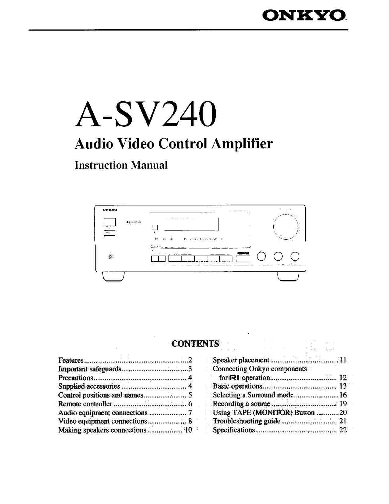
Onkyo ASV 240 Owners Manual

Extracted text from Onkyo ASV 240 Owners Manual (Ocr-read)


Page 1

A-SV24O

Audio Video Control Amplifier

Instruction Manual


:1 m
O:
\_J
CONTENTS

Features ........................................................ 2 Speaker placement..............L.....=.;..,,...g........f 11
Important mfeguards 3 Connecting Onkyo components
Pmcanfions ............. 4 fort-=21 operation. ' 12
Supplied accessones .......... 4 Basic operations ......... 13
Comm! positions and names .. 5 Selecting a Surround mode ..... . 16
Remote conuoller ................. *. .. 6 Recording 3 source .V'. ............ 19
Audio equipment connections .. 7 Using TAPE (MONITOR) Button 20
Video equipment connections.... .1 8 Troubleshooting guide .................. 21
Making speakers connections ................... 10 Specifications ............................................ 22

Page 2

Thank you you for purchasing the Onkyo
Audio Video Control Amplifier

Please read this manual thoroughly before making con-
nections and turning on the power.

Following the instructions in this manual will enable
you to obtain optimum performance and listening enjoy-
ment from your new Audio Video Control Amplifier.
Please retain this manual for future reference.

Features

Power Output:
Stereo mode
100 watts per channel, min. RMS into 8 ohms, both
channels driven from 20 Hz to 20 kHz with no more
than 0.08% THD
Surround Mode (MULTI-CH INPUT)
Front L/R and Center Channel
80 W (20 Hz - 20 kHz 0.08%, 8 ohms)
Rear Channel (Rear Channel only driven)
20 W (20 Hz - 20 kHz. 0.1%, 8 ohms)

Low Impedance Drive Output Stage (Front L/R)

All Discrete Power Amp Stage

Input Terminals for 2 Video and 4 Audio sources
Dolby *Pro Logic and Hall surround

Adjustable Digital Delay

Subwoofer Preout Terminal

Audio 1PM on/off

MULTI-CH INPUT (Front LfR CENTER, Rear L/R, Sub-
woofer)

* Manuluctured under license from Dolby Laboratories Licensing Corr

poraiion. "Dolby". the double-D symbol DD. and Pro Logic" are
trademarks of Dolby Laboratories Licensing Corporation

Replacement and mounting of an AC plug on the power supply cord
of this unit should be performed only by qualified service personnel.
0 IMPORTANT
The wires in the mains lead are coloured in accordance With the
following code:

Blue: Neutral

Brown: Live
As the colours of the wires in the mains lead of this apparatus may
not correspond with the coloured markings identifying the termi-
nals in your plug. proceed as follows:
The wire which is coloured blue must be connected to the terminal
which is marked with the letter N or coloured black.
The wire which is coloured brown must be connected to the terminal
which is marked with the letter L or coloured red.

IMPORTANT

A 5 amp fuse is fitted in this plugi Should the fuse need to be
replaced. please ensure that the replacement fuse has a rating of 5
amps and that it is approved by ASTA or BSl to 881362. Check
for the ASTA mark or the BSI mark on the body of the fuse.

IF THE FITTED MOULDED PLUG [S UNSUITABLE FOR
THE SOCKET OUTLET IN YOUR HOME THEN THE FUSE
SHOULD BE REMOVED AND THE PLUG CUT OFF AND
DISPOSED OF SAFELY. THERE IS A DANGER OF SEVERE

ELECTRICAL SHOCK IF THE CUT OFF PLUG IS INSERTED
INTO ANY 13 AMP SOCKET.
If in any doubt please consult a qualified electrician.


Note to CATV system installer:

o This reminder is provided to call the CATV system installer's
attention to Section 820-40 of the NEC which provides guide
lines for proper grounding and. in particular. specifies that the
cable ground shall be connected to the grounding system of the
building, as close to the point of cable entry as practical,

FCC Information for User

CAUTION:

Changes or modifications not expressly approved by the manu-
facturer for compliance could void the user's authority to upere
ate the equipment.

NOTE:
This equipment has been tested and found to comply with the
limits for a Class B digital device, pursuant to Part [5 of the
FCC Rules. These limits are designed to provide reasonable
protection against harmful interference in a residential installae
tion. This equipment generates. uses, and can radiate ratio fre
quency energy and. if not installed and used in accordance With
the instructions. may cause harmful interference to radio come
munications. Howeveri there is no guarantee that interference
will not occur in a particular installation. If this equipment dose
cause harmful interference to radio or television reception.
which can be determined by turning the equipment off and on.
the user is encouraged to try to correct the interference by one
or more of the following measures:

0 Reorient or relocate the receiving antenna.

0 Increase the separation between other equ1pment and receiver,

0 Connect the equipment into an outlet on a circuit different

from that to which other receiver is connected

0 Consult the dealer or an experienced radio/TV technician for

help,

o For models having a power cord with a polarized plug.
CAUTION: TO PREVENT ELECTRIC SHOCK. MATCH
WIDE BLADE OF PLUG TO WIDE SLOT. FULLY INSERT.

o Sur les modeles dont la fiche est polarisée.
ATTENTION: POUR EVITER LES CHOCS ELECE
TRIQUES, INTRODUIRE LA LAME LA PLUS LARGE DE LA
FICHE DANS LA BORNE CORRESPONDANTE DE LA
PRISE ET POUSSER JUSQUAU FOND.