Onkyo ARV 400 Service Manual

This is the 17 pages manual for Onkyo ARV 400 Service Manual.
Read or download the pdf for free. If you want to contribute, please upload pdfs to audioservicemanuals.wetransfer.com.

Page: 1 / 17
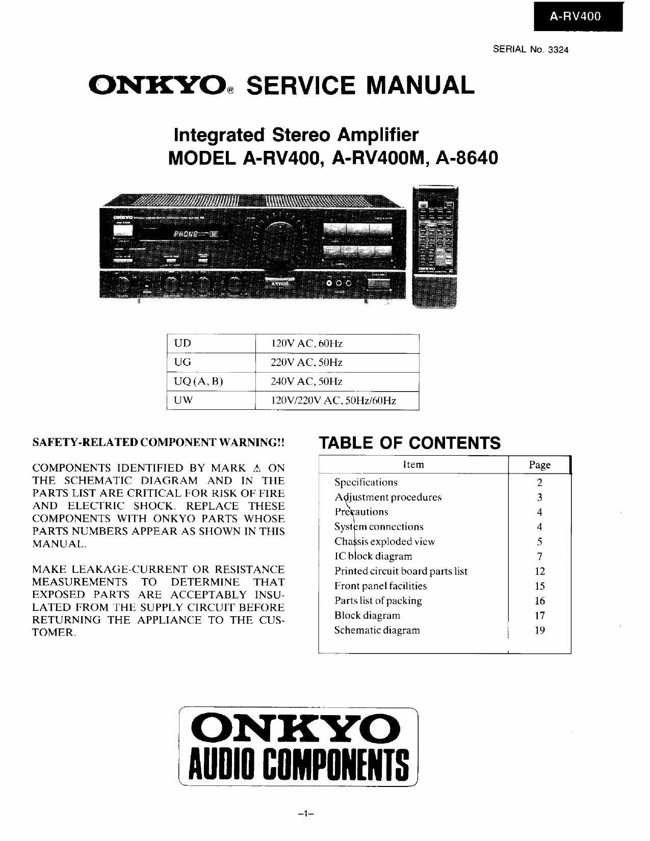
Onkyo ARV 400 Service Manual

Extracted text from Onkyo ARV 400 Service Manual (Ocr-read)


Page 1

A-RV400

SERIAL No. 3324

ONKYO@ SERVICE MANUAL

Integrated Stereo Amplifier
MODEL A-RV400, A-RV400M, A-8640

7' UD7 I 120v AC. (IOHZ
U6 7 220v AC. 50Hz
-UQ(A. B) V 240v ACI.S6HZ
I UW 7 . l?(]V/22(JV ACSOIIz/mHz

SAFETY-RELATEDCOMPONENTWARNING!! TABLE OF CONTENTS

COMPONENTS IDENTIFIED BY MARK 12. ON w "em Page
THE SCHEMATIC DIAGRAM AND IN THE Specifications 2
PARTS LIST ARE CRITICAL FOR RISK OF FIRE Adjuslmem procedures 3
AND ELECTRIC SHOCK. REPLACE THESE Pagaunom 4
COMPONENTS WITH ONKYO PARTS WHOSE : , . ,
PARTS NUMBERS APPEAR AS SHOWN IN THIS 535?" "10 4
MANUAL. Cha Sis exploded View 5
[C block diagram 7
MAKE LEAKAGE-CURRENT 0R RESISTANCE Prinlcdcircuit board partslist 12
MEASUREMENTS TO DETERMINE THAT Fronwanelfadmics 15
EXPOSED PARTS ARE ACCEPTABLY INSU- Pamlismf ackin 16
LATED FROM THE SUPPLY CIRCUIT BEFORE M, F g
RETURNING THE APPLIANCE To THE CUS- 3 gm" '7
TOMERI Schematicdiagram I 19

; ONKYO
i Alllllll BflMPflNHflS

Page 9

LC6538D
Pin No liu uamc Symbol Function

1 'llft/Slt) SK Segmentoutput terminals. Active: H

2 TI Z/Sl I SI

3 "I'll DISPLAY Display control output terminal. "I I" when display is illurninatcd.

4 [10 DIRECT Direct display output terminal. H" when direct is on.

5 T) FM FM control output terminal (receiver only). H" wlten set to FM. Controls
the automatic reception mode display.

6 TR [)9 Digit output terminals. Active: IH Key scan output terminals.

7 T7 D8

8 To D7

) 'I'S Du

ltl T4 [)5

| l 1'} D4

l2 '1'2 [)3

l3 'll D2

l4 Ttl DI

15 V.,,, VI," lowel supply terminztl(+5V)

1t! ()SCI ()SCI Main system clock te rmin: '. Connected to 4 M Hz ceramic oscillator. The

17 OSC2 OSCZ systemclock mode is equivalentto the main clock 2 mode (cycle time: 2ls).

l8 V V55 Ground term

I) TEST TESI LSI test Ierml 1 Connected to V.

21) RES RES Reset input terminal. Active: L. 0

2| XI X1 Sub»cloek teI' tls. Not used. XI ternlinal iscoimecttcd V.,.,.

22 X2 X2

23 PG) L AL Automatic reception modedisplay output terminals. Active: L. L" when

24 ICl :D'X 7 in automatic reception mode (receiver only). (The settings tor DX and

25 ICZ AUTQ LOCAL as well as AUTO and MONO are always the reverse of one

26 PC} MONO another.) Allare always L" loramplilier.

27 IDU POWER POWER signal output terminal. H" when ON.

28 PDI RELAY Smakerrelaycontrol output terminal. Active

2) PD] VDt Video signal control output terminals. Active: H.

3|] ID} VDl

3| IAt) K0 Key input terminals. Active: H".

31 lAl Kl

33 lA2 K2

34 |/\3 K3

35 PB S5 Station detect input terminal (rcccivcronly). Active: l .Turnsotlauto
tuning.

3ft tlil Stereo broadcast detect tel initial. Active: L". Controls STEREO

. indication (receiveronly).

37 ll32 RF IN RFinputterminal (receiveronly). DX when H".

38 I'll} REC/AMP Initial settinginput terminals.

3) IEtl/VREFU BACK

40 lEl/VREFI FHONO PHONOcontrol output terminal. L" when selector is setlo PHONO.

41 IEZ/STA RT A m/MONO/ r: AUTO/MONO switching output terminal 1." when AUTO

TAPE 2 t ronly)
(2) Ampl ier: TAIEQ control output terminal. L when TA lE-Z is on.
g>i42 llitl/Sltl SEL Output terminal connected to analog switch LC7821 CE terminal.

43 IFl/SOt) DATA Output terminal connected to DATA terminal oi PLL LM700I and DI
terminal of switch LC782 |.

44 lFZ/SCKO CL Output terminal connected to CL terminals of PLL LM7tlUl and switch
LC782 l.

J5 lFJ/INTO ILL Receiver: outputterminal connected to CEterminalol'PLL LM7UUI.

4r. lCtl/Sll DlRECT Dl RECT control output terminal, Active: "L.

47 lGl/SOI lNlMUT INPUT selector muting output terminal. Active: H.

48 KHZ/SEW RE MUT Record outputmuting output terminal. Acitvc: H

~19 l(i3/lN'll l6 E lowerollscnsor input terminal. Active: L. L shorter than ltXlus is
ignored.

5t] llltt/DACU TU MUT Tuner muting output terminal (receiveronly). Active:H".

5] H l l/l)ACI PROTECT lrotect operation sensor input terminal. "ll during protect operation. H"
shorter than ltltlus is ignored. Controls RELAY output.

52 Pl ll/SOR SYS IN Systemcode input terminal. Active: H.

53 Pl l3/l [(N'l' SYS OUT! System code output terminal. Active: L. Becomes at setting input

SYS EN terminal SYS EN when poweristurned on.

54 St! Sa Segment output terminals. Active: H.

55 5] Sb

56 SI Sc

57 S} Sd

58 SJ Sc

59 55 St

()0 St) St;

at 57 Sh

(72 VP Vl Power supply terminal {or pull down resistance.

63 T1 5/88 Si Segment output terminals. Active: H".

(7-1 'I'l-1/S9 Sj

-9-

A-RV400