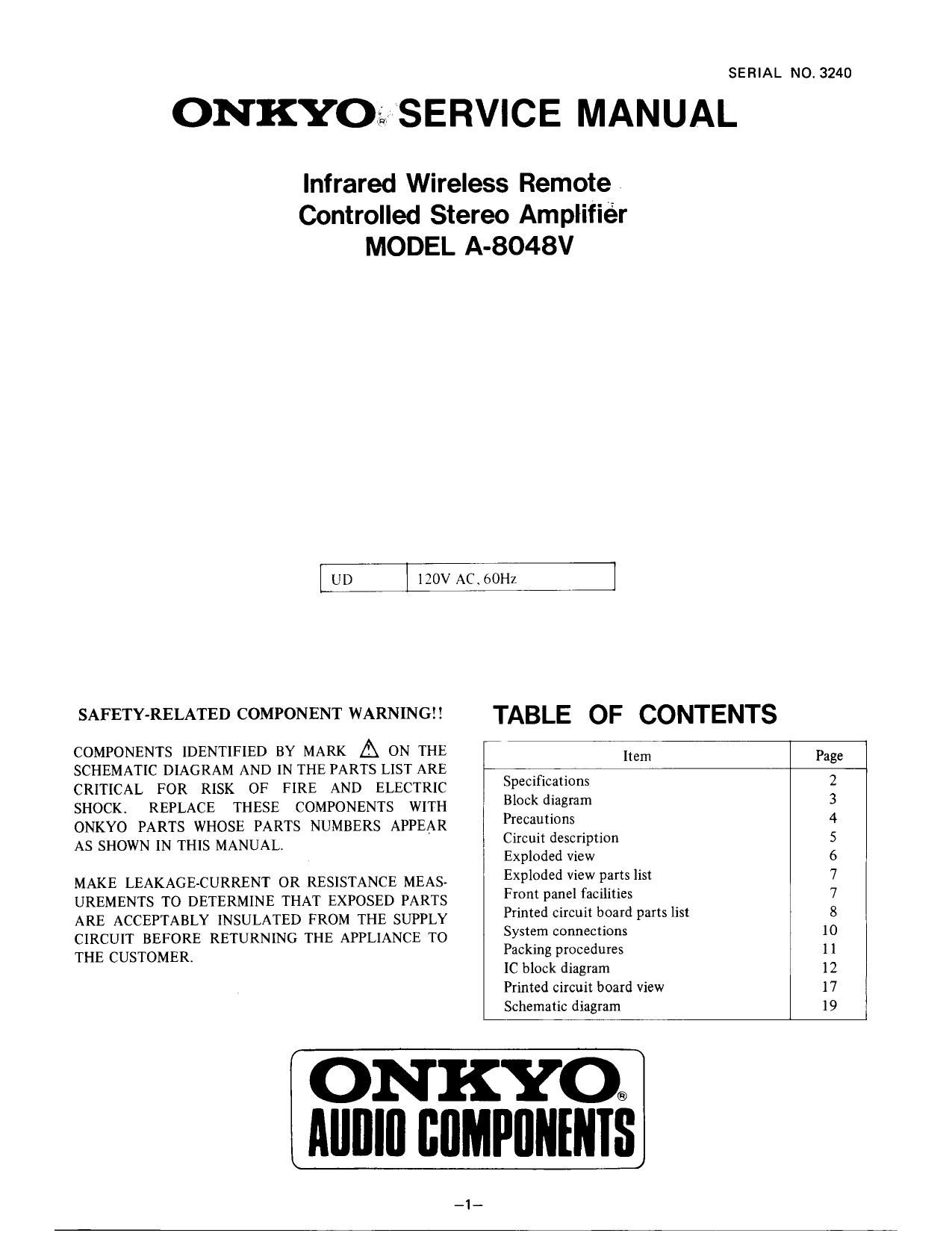
Onkyo A 8048 V Service Manual
This is the 12 pages manual for Onkyo A 8048 V Service Manual.
Read or download the pdf for free. If you want to contribute, please upload pdfs to audioservicemanuals.wetransfer.com.
Extracted text from Onkyo A 8048 V Service Manual (Ocr-read)
Page 1
SERIAL NO. 3240
ONKYOz: SERVICE MANUAL
Infrared Wireless Remote .
Controlled Stereo Amplifier
MODEL A-8048V
UD 120V AC. bOHz
SAFETY-RELATED COMPONENT WARNING!! TABLE OF CONTENTS
COMPONENTS IDENTIFIED BY MARK A ON THE am Page
SCHEMATIC DIAGRAM AND IN THE PARTS LIST ARE _ _
CRITICAL FOR RISK OF FIRE AND ELECTRIC Spemficgtmns 2
SHOCK. REPLACE THESE COMPONENTS WITH Block diagram 3
ONKYO PARTS WHOSE PARTS NUMBERS APPEAR Precaunons 4
As SHOWN IN THIS MANUAL Circuit description 5
Exploded view 6
MAKE LEAKAGE-CURRENT OR RESISTANCE MEAS- Exploded View Pjflfshsl 7
UREMENTS TO DETERMINE THAT EXPOSED PARTS Fiompatfel faCIlltles . 7
ARE ACCEPTABLY INSULATED FROM THE SUPPLY Primed 01mm Ward Partshst 8
CIRCUIT BEFORE RETURNING THE APPLIANCE TO Sysiém connections 10
THE CUSTOMER. Packmg procedures 1 1
[C block diagram 12
Printed circuit board View 17
Schematic diagram 19
ON KYO:
Mllllll BIIMPIINENIS
Page 2
SPECIFICATIONS
Power Output: 105 watts per channel, min. RMS, at 8 ohms, both channels driven, from 20Hz to 20kHz,
with no more than 0.09% THD
Total Harmonic Distortion: 009% at 105 watts
IM Distortion: 0.09% at 105 watts
Damping Factor: 40 at 8 ohms
Frequency Response: 15 - 30,000 Hz i 1 dB
Sensitivity and Impedance: Phono: 2.5 mV/SO kohms
Tape Play: 150 mV/SO kohms
Tape Rec: 150 mV/3.5 kohms (phono)
Phono Overload: 150 mV RMS at 1 kHz, 0.09% THD
Bass Control: :8 dB at 100 Hz
Treble Control: 18 dB at 10.000 Hz
Remote Control Transmitter PIC-48A
Transmitter: Infrared
Signal range: Approx. 5 meters, 16 ft. 4"
Power supply: Two AA batteries (1.5V x 2)
Dimensions (W x H x D): 40 x 18 x 145 mm
1-1/2 x 1/4 x 5-5/8
Weight: 90 grams, 3.2 oz. (including batteries)
Signal to Noise Ratio: Phono: 75 dB (IHFA-ZOZ, 5 mV input, 1 watt output)
Tape Play: 80 dB (IHF A-202, 0.5V input, 1 watt output)
Loudness Control: +6 dB at 70 Hz, +5 dB at 10 kHz
Audio Muting: _20 dB
General
Power Supply: AC 120V, 60Hz
Dimensions (W x H x D): 435 x 112 x 279 mm
17-1/8 x 4-7/16 X 10-15/16"
Weight: 7.8 kg. (17.2 lbs.)
Specifications and features are subject to change without notice.
_2_
Page 7
A-8048V
CHASSIS-EXPLODED VIEW
Page 8
CHASSIS-EXPLODED VIEW PARTS
REF. NO. PART NO.
A1 27110289A
A2 2711519371
A3 27130404-1
A6 27160191A
A7 2714102013
A8 27141077
A10 27120890
A11 27300750
A14 27190472A
A18 838430080
A19 834430068
A25 82143006
A26 800509
A500 17808121
A503 27262414
A506 27262415
A510 28184295
A511 834430068
A601 2717020871
A602 27175028
A603 834430088
A825 28322620A
A831 28322621A
A835 28322622A
A836 28321905B
A837 28322623A
Q501,Q601 222051
ATQOI 2300124
AIFQOI 252052
DESCRIPTION REF. NO.
Front bracket APQOI
Side bracket
Bracket (PT)
Radiator APBOZ
Bracket (HE) U1
Bracket (S)
Back panel U2
Bushing (cable)
Holder (POW) U3
3T'IB+8P(BC), Tapping screw
3TTS+6B(BC). Tapping screw U4
3P+6FN(BC), Screw
Pin U5
Front panel assy
Plate (POW) U6
Plate (T)
Top cover U7
3TTS+SB(BC), Tapping screw
Bottom board U8
Bottom leg
3TTS+6B(BC), Tapping screw U9
Knob assy, VOL
LIST
PART NO. DESCRIPTION
253123 or ASUCS $118, Power supply cable or
253136 or ASUCS 1118. Power supply cable or
253140 AS-UC-S 1118. Power supply cable
25050293 NSCT6P120. AC outlet
178085071 NAMA2707r1, Equalizer 8: power
amplifier pc board assy
178085081 NASW2708*1, Selector/Monitor
switch pc board ass'y
17808509-1 NATC-2709r1, Tone controle circuit
pc board assy
17808510'1 NAVRZiIOI, Volume controle pc
board assy
17808511-1 NADIS27111, Display LED pc board
ass'y
17808512rl NAHP2712rl, Speaker switch pc
board assy
1780851371 NASW-Z713-1. Standrby relay pc
board assy
178085141 NAPJ*2714*1, VCR] input terminal
pc board assy
17808515-1 NAVDrZ7151, Video switch circuit
pc board assy
1780851671 NAVR-2716>1, Nois filter circuit pc
board assy
178085171 NADIS-2717rl, LED pc board assy
Knob assy, SP U10
Knob, TONE
Knob, POW U11
Knob, PUSH
STK'4044V. IC NOTE:
NPT926D. Power transformer
7A(ST*6), Primary fuse
THE COMPONENTS IDENTIFIED BY MARK A ARE
CRITICAL FOR RISK OF FIRE AND ELECTRIC
SHOCK. REPLACE ONLY WITH PARTS NUMBER
SPECIFIED.
FRONT PANEL FACILITIES
1 ES
ONKYU FRARED WIRELESS
mums 5";
gym"
El T41 @
rs comm
BALANCE
qumc _.
fl
vca (/voP
©©©
macaw
El IE I 1 011 El E E
1. Power Switch (POWER) 11. VCR or Video Disc Player Input Jack
ON/OFF (VCRI/VDP)
2. Speaker Selector (SPEAKERS) 12. Input Selector Switches and Indicators
OFF, A, B, A+B (INPUT SELECTOR)
. '1 Headphone Jack (PHONES) Audio Selector
L 4. Bass Control (BASS) PHONO, CD, TUNER
5. Treble Control (T REBLE) Video Selectors (Control audio and
6 Balance Control (BALANCE) video signals)
7 Volume Control and Indicator VCRl/VDP. VCR-2
(VOLUME) 13. Remote Control Sensor
8. Loudness Control (LOUDNESS) 14. StandrBy Receive Indicator
ON/OFF 15. Muting Indicator
9. Simulated Stereo (SIMULATED 16. Power Level
STEREO) ON/OFF 17. Power Key
10. Tape Monitor Switch and Indicator 18. Volume UPI)OWN Key
(MONITOR) UP, DOWN
TAPEI. TAPEZ/EQ
_7_
19. Audio Muting Key