Onkyo A 7 Service Manual

This is the 8 pages manual for Onkyo A 7 Service Manual.
Read or download the pdf for free. If you want to contribute, please upload pdfs to audioservicemanuals.wetransfer.com.

Page: 1 / 8
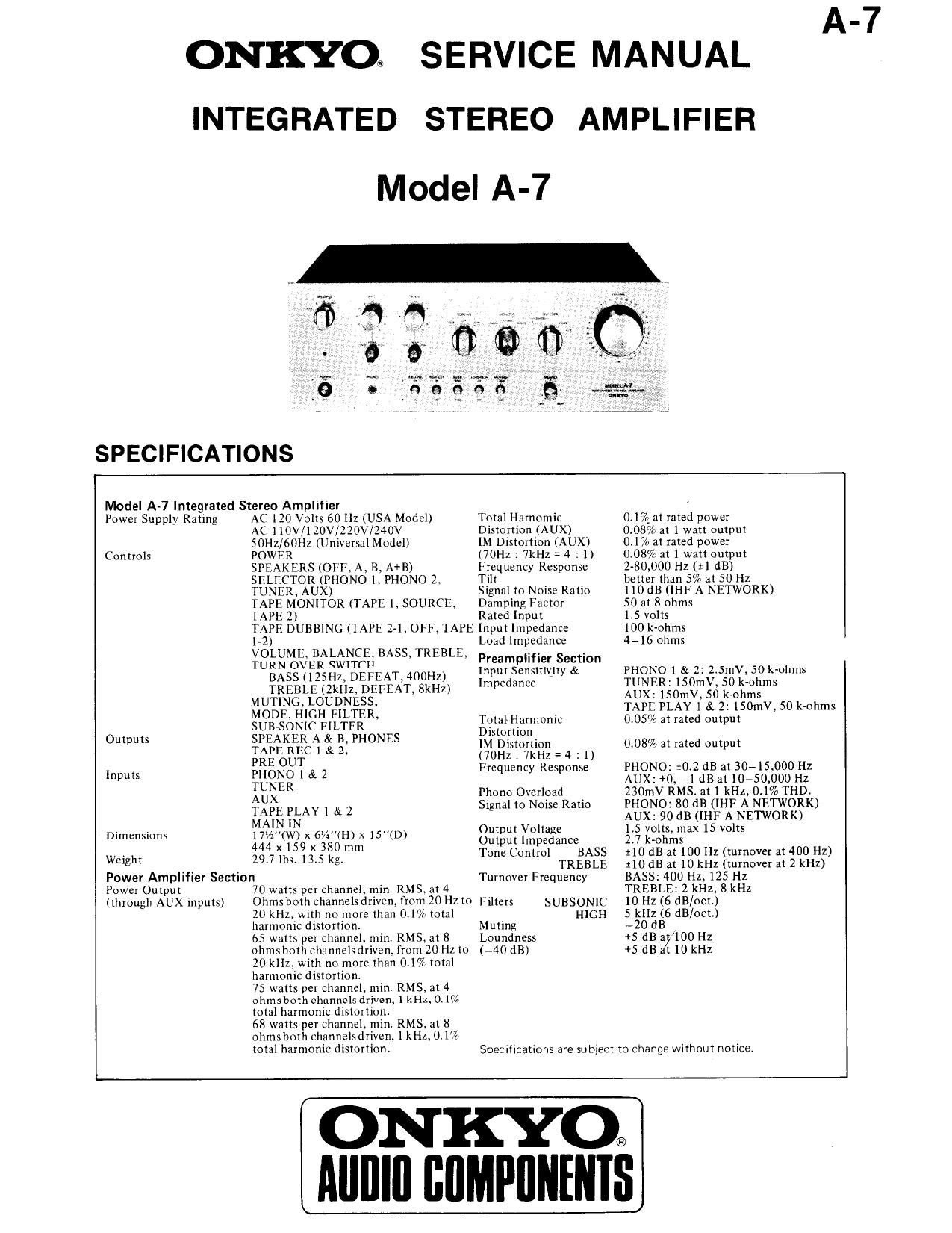
Onkyo A 7 Service Manual

Extracted text from Onkyo A 7 Service Manual (Ocr-read)


Page 2

A-7

SERVICE PROCEDURES

1.

Checking the operation of the protective circuit.

The protective circuit of the A-7 works in the following manner: A fuse burns out if speaker of too low impedance are con-

nected. or if the speaker wires are accidentally shorted. A relay cuts-off output from the amplifier if due to malfunction DC

current appears at the output terminals. The relays will also be actuated in the event of excessive output current. A check of

the protective circuit is made by placing the unit in the following sequence of settings.

1)
2)
3)
4)
5)

No load.

Set all controls at the levels set on the power amplifier (refer to power amplifier).

Set the SELECTOR switch to PHONO.

Apply a 5H2, 1V (RMS) sine wave to the PHONO inputs.

Gradually increase the setting of the master volume control. The protective circuit relay should activate as a result of this.

Note: Operation of tht protective circuit relay can also be checked by setting the center voltage at DC 4V and removing the

fuses F701 and F 702, and then applying a DC tSV voltage to the output terminals. This should actuate the relay.

2.
1)
2)
3)

4)

Checking the circuit board of the power amplifier.

Remove two lower screws from the heat sink.

Remove two screws on the hack of the heat sink.

Remove two heat-sensor transistors Q613 and 0614 from the heat sink. If they cannot be pulled out, remove two
mounting screws from the transistor sockets.

The check can also be performed by fastening it as shown in Fig. l with screws that have been removed.

Screw Fig. 1

The screws used to fasten the bus grounding strips and the terminals of the power supply electrolytic capacitor have can
influence sound quality. They must be tightened securelyr
When replacing differential amplifier or push-pull amplifier transistors. be sure that transistors of both channels have the

the same hpE ratings.