Onkyo A 5 Service Manual

This is the 8 pages manual for Onkyo A 5 Service Manual.
Read or download the pdf for free. If you want to contribute, please upload pdfs to audioservicemanuals.wetransfer.com.

Page: 1 / 8
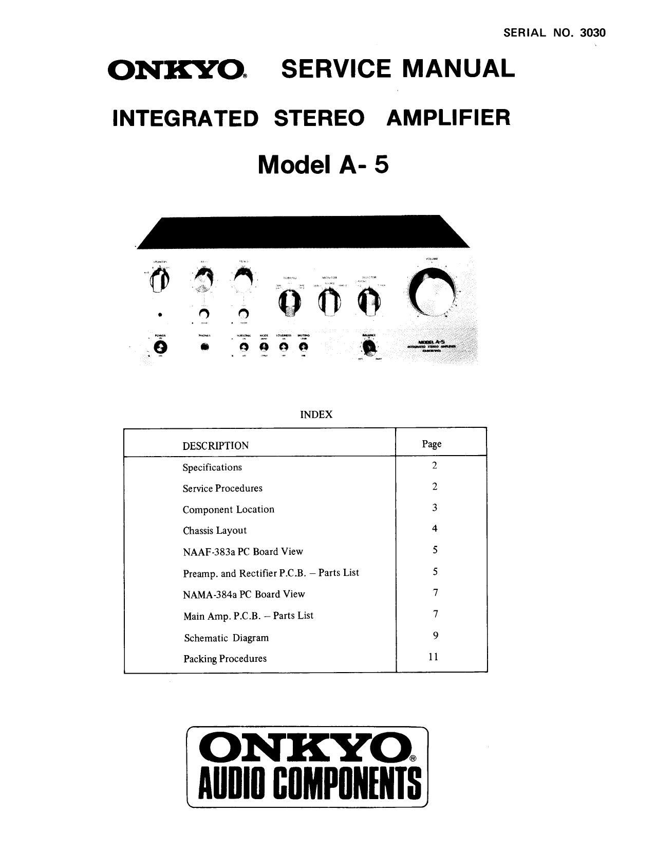
Onkyo A 5 Service Manual

Extracted text from Onkyo A 5 Service Manual (Ocr-read)


Page 1

SERIAL NO. 3030

ONKYOQ SERVICE MANUAL

INTEGRATED STEREO AMPLIFIER
Model A- 5

INDEX
DESCRIPTION Page
Specifications 2
Service Procedures 2
Component Location 3
Chassis Layout 4
NAAF-383a PC Board View 5
Preamp. and Rectifier P.C.B, - Parts List 5
NAMA-384a PC Board View 7
Main Amp. P.C.B. - Parts List 7
Schematic Diagram 9
Packing Procedures I 1

ONKYO®
AIIIIIII IIIIMPIIIIIIIIS

Page 2

SPECIFICATIONS

Power Amplifier Section

Continuous

Dynamic

Total Harmonic
Distortion

lM Distortion
(70Hz:7kHz=4:l)
Frequency Response
Tilt of Square Wave
Signal to Noise Ratio
Damping Factor
Input Impedance
Rated Input

Load Impedance

60 watts per channel, min. RMSm

4 ohms, both channels driven, lkHz,
0.1% THD.

50 watts per channel, min. RMS, at

8 ohms, both channels, driven, lkHz
0.1% THD.

50 watts per channel, min. RMS,at

4 ohms, both channels driven, from
20112 to 20kHz, 0.1% THDI

45 watts per channel, min. RMS. at

8 ohms, both channels driven, from
20Hz to 20kHz, 0.1% THD.

250 watts total at 4 ohms 1%

THDI (DIN)

160 watts total at 8 ohms 1%

THD. (DIN)

220 watts total at 4 ohms 0.1% THD.
150 watts total at 8 ohms 0.1% THD.

0.1% at rated power
0.08% at 1 watt output

008% at 1 watt output
2A7O,000IIZ (11:13)

better than 5% at SOHZ
110dB(11-1F A NETWORK)
50 at 8 ohms

25 k-ohms

1.5 volts

4-16 ohms

Preamplifier Section
Input Sensitivity &
Impedance

Total Harmonic
Distortion

1M Distortion
(70Hz: 7kHz=4: 1)

Frequency Response

Phone Overload
Signal to Noise Ratio

Tone Controls
BASS

TREBLE

Output Voltage
Output Impedance
Subsonic Filter
Muting

Loundness (740dB)

General
Power Supply

Dimensions
(w x H x D)
Net Weight

PHONO 18L 2: 2.5mV, 50 190th
TUNER: lSOmV, 50 k~ohms
TAPE PLAY 1 & 2: lSOmV,

SO k-ohms

0.08% at rated output

0.08% at rated output

PHONO: :0.3dB at 30-IS,000HZ
TUNER: 15740,000Hz(+0,71dB)
170mV RMS at lkHz, 01% THD
PHONO: 75dB (IHF A NETWORK)
TUNER: 90dB (IHF A NETWORK)

tIOdB at IOOHZ
thdB at IOkHz
1.5 volts

2.2 k-ohrns
10Hz (6dB/oct.)
«ZOdB

+5dB at 1001lz
+5dB at lOkHz

AC 110/120/220/240V, 50/60Hzr
(Universal Model)

AC 120V. 60Hz (U,S.A. Model)
444 x159 x 380mm

(I7/2" x694 x15")

I212kg (269 lbs.)

Specifications and features are subject to change without notice.

SERVICE PROCEDURES

1.
1)

2)

3)

4)

Checking the circuit board of the power amplifier.

Remove two lower screws from the heat sink.

Remove two screws on the back of the heat sink.

Remove two heat-sensor transistors 0613 and 0614 from the heat sink. If they cannot be pulled out, remove two

mounting screws from the transistor sockets.

The check can also be performed by fastening it as shown in Fig. l with screws that have been removed.

Screw

2-

Fig. 1