Nikko na 2000 int sm

This is the 14 pages manual for Nikko na 2000 int sm.
Read or download the pdf for free. If you want to contribute, please upload pdfs to audioservicemanuals.wetransfer.com.

Page: 1 / 14
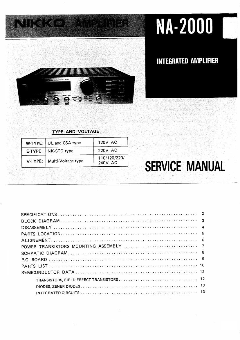
Nikko na 2000 int sm

Extracted text from Nikko na 2000 int sm (Ocr-read)


Page 1

NA-ZIIUI]

' '_ TYPE AND VOLTAéE

INTEEBIITED AMPLIFIER

W-TYPE: UL and CSA type 120V AC
E-TYPE: NK-STD type 220V AC
V-TYPE: MuIti~Voltage type £130 ZAO/CZZO/ SERVICE MANUAL
SPECIFICATIONS .......................................................... 2
BLOCK DIAGRAM ......................................................... 3
DISASSEMBLY ............................................................ 4
PARTS LOCATION ......................................................... 5
ALIGNEMENT ............................................................. 5
POWER TRANSISTORS MOUNTING ASSEMBLY ............................... 7
SCHMATIC DIAGRAM ...................................................... 3
PC. BOARD ............... 9
PARTS LIST .............................................................. 1o
SEMICONDUCTOR DATA ................................................... 12
TRANSISTORS, FIELD EFFECT TRANSISTORS ................................. 12
DIODES, ZENER DIODES ................................................. I3

INTEGRATED CIRCUITS ................................................. 13

Page 2

I -2000

SAFETY INSTRUCTION

PRECAUTIONS DURING SERVICING

, 1. Parts identified by the symbol parts are critical for When replacing the primary components (transformer.
safety. Replace only with same parts number specified. Power supply cord, SWlTCIl, SWitCh bV-PBSS CEPBCIIDI.
2. Other parts and assemblies are specified for con- etc') wrap 7nd 0f wires securely about the terminals
formance with such regulations as those applying before soldering. _ _ g _ _ '
to spurious radiation. Where hand solderlng is Involved a minimum spacrng
These must also be replaced only with replacements. beiow between Wm?" of uninsulated I've Fans Of
Examples: RF converters, tuner units, RF cables, primary Drsupply Circuitry through air or over surface
noise blocking capacitors, noise blocking '5 to be maintained.
filters, etc. 110 and 120V appliance: more than 3 mm spacing
3. Use specified internal wiring. 220 and 240V appliance: more than 6 mm spacing
a) Primary leads. Observe that wires do not contact heat producing parts
b) Wires covered with PVC tubing. (heatsinks, oxide metal resistors, rectifiers, etc.)
c) Double insulated wire. Check that replaced wires do not contact sharp edge or
4. Use specified insulating materials for hazardous live pointed parts.

parts.

a) Insulation Taps.

b) Insulated Barriers (Spacers)

0) PVC Tubing.

d) Plastic screws for fixing microswitch (Especially
in turntable).

e) Terminal strips.

Do not remain an electric conductive parts (screws,
droplets, etc.) inside the appliance.

SAFETY RECHECK AFTER SERVICING

Confirm the specified insulation resistance between power
plug prongs and externally exposed parts of the appliance
is greater than 10M ohms, but for equipment with external
antenna terminals (tuner, receiver, etc.) and is specified
insulation resistance should be more than 2.2M ohms
(ground terminals, in-output lacks, etc.)