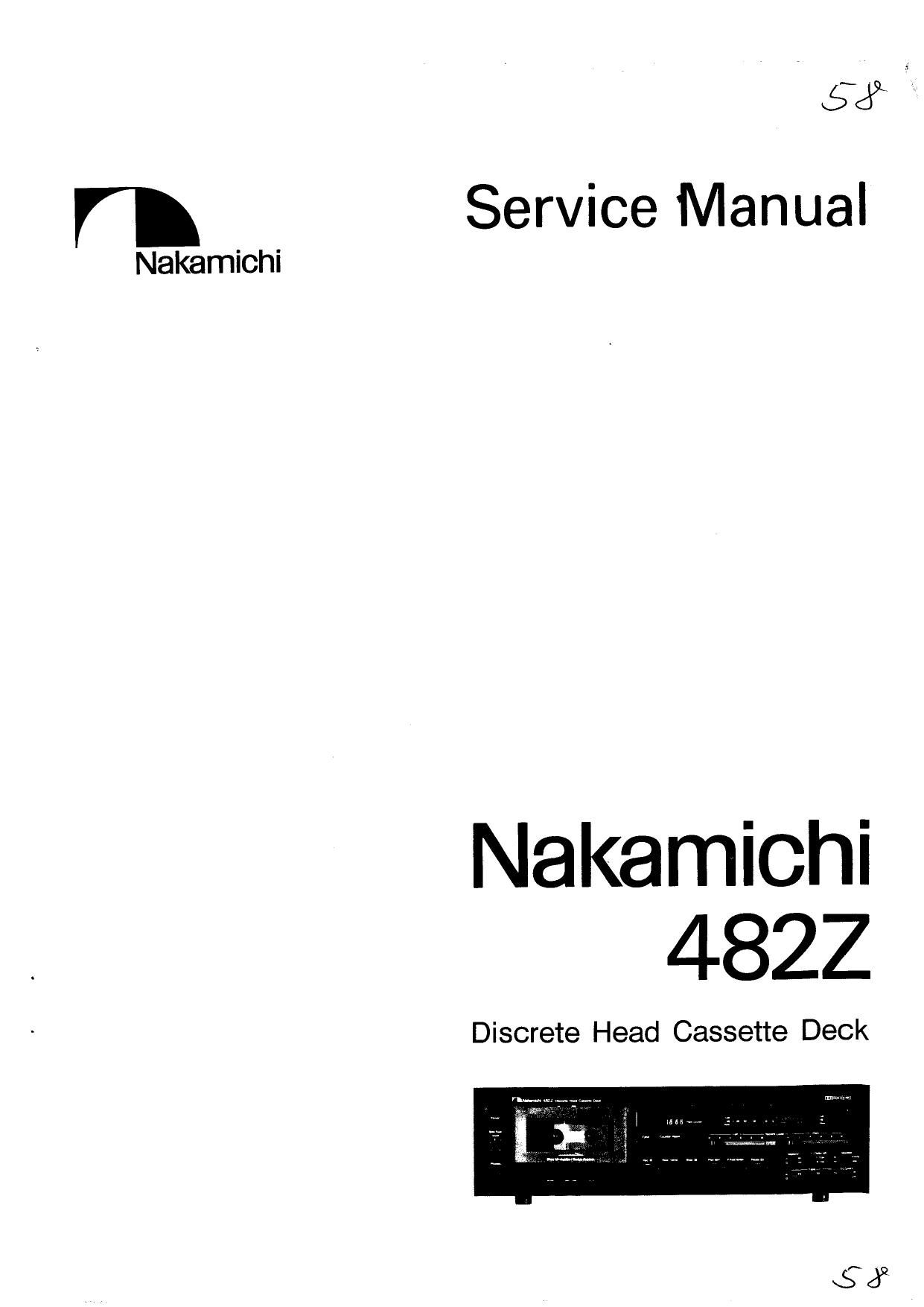
Nakamichi 482 Z Service Manual
This is the 63 pages manual for Nakamichi 482 Z Service Manual.
Read or download the pdf for free. If you want to contribute, please upload pdfs to audioservicemanuals.wetransfer.com.
Extracted text from Nakamichi 482 Z Service Manual (Ocr-read)
Page 1
V 53
Service Manual
Nakamichi
Nakamichi
4822
Discrete Head Cassette Deck
Page 2
CONTENTS
1. General ...................................................................... 3
2. Removal Procedures ..................................................... 4
2. 1. Cassette Case Cover Ass'y ................................................ 4
2. 2. Top Cover Assy .................................................... 4
2. 3. Bottom Cover Assy ................................................. 4
2. 4. Front Panel Ass'y ..................................................... 5
2. 5. Headphone Jack Ass'y .................................................... 5
2. E. Mechanism Ass'y ....................................................... 5
2. 7. Level Indicator Ass'y, Lamp P.C.B. Assy and Indicator P.C.B. Ass'y ..................... 5
2. 8. Logic P.C.B. Assy, Headphone Switch P.C.B. Assy and MPX Filter Switch P.C.B. Ass'y ........ 5
2. 9. Main P.C.B. Assy ....................................................... 6
2. 10. Control Switch Holder Assy ................................................ 6
2. 11. Switch P.C.B. Ass'y ...................................................... 6
2. 12. Volume P.C.B. Assy and Control Switch P.C.B. Ass'y ............................... 6
2. 13. Bias Oscillator P.C.B. Assy ................................................. 6
2. 14. Rear Panel Assy, Power Transformer and Power Switch 8
2. 15. Cassette Case Assy and Cover Plate Assy .................................. 8
2. 16. Tape Counter Ass'y ................................................. . . . 8
2. 17. Capstan Motor Assy and Flywheel Ass'y ....................................... 8
2. 18. Sub Mechanism Chassis Assy ............................................... 9
2. 19. Control Motor Assy and Reel Motor Ass'y ...... 9
2. 20. Cam Control Volume .................... 9
2. 21. Reel Hub Assy and Idler Assy ........ 9
2. 22. Cam Drive Gear and Control Cam ............................................ 10
2. 23. Head Mount Base Ass'y ................................................... 10
2. 24. Pressure Roller Ass'y and Erase Head .................... 10
2. 25. Playback Head Assy and Record Head Assy ............... 10
3. Measurement Instruments ................................... 11
4. Mechanical Adjustments .......................................................... 12
4. 1. Mechanism Control Cam Adjustment .......................................... 12
4. 2. Tape Speed Adjustment ................................................... 13
4. 3. Record Head and Playback Head Tilt Adjustment .................................. 13
4. 4. Head Base Stroke Adjustment ............................ 15
4. 5. Tape Guides Adjustment and Erase Head Stroke Adjustment ....... 16
4. 6. Erase Head Height and Tilt Adjustment ..................... 17
4. 7. Back Tension Adjustment ................................................. 18
4. 8. Playback Head and Record Head Height Adjustment and Azimuth Alignment ............... 19
4. 9. Record Head Stroke Adjustment ............................................. 20
4. 10. Tape Travelling Adjustment ............................................. 21
4. 11. Flywheel Holder Adjustment .......................................... 21
4. 12. Eject Wire Adjustment .........
4. 13. Lubrication ................
5. Parts Location for Electrical Adjustment .....
6. Electrical Adjustments and Measurements ..................... 24
6. 1. Adjustment and Measurement Instructions ............ 24
6. 2. Playback Frequency Response Adjustment ...................................... 27
6. 3. Dolby NR Circuit Check .................................................. 28
7. Mounting Diagrams and Parts List .................................................... 29
7. 1. Main P.C.B. Assy ..................................................... 29
7. 2. Logic P.C.B. Ass'y ............................................... . . 33
7. 3. Volume P.C.B. Assy ................................................... 35
7. 4. Lamp P.C.B. Ass'y .................................................... 35
7. 5. MPX Filter Switch P.C.B. Assy .............................................. 35
7. 6. Headphone Switch P.C.B. Ass'v .............................................. 35
7. 7. Bias Tune Volume P.C.B. Ass'y .................................... . . 35
7. 8. Indicator P.C.B. Assy .................................................... 35
Page 17
4.5.
Tape Guides Adjustment and Erase Head Stroke
Adjustment
Remove Head Mount Base Ass'y referring to item 2.23.
Refer to Figs. 4.8 and 4.9.
(1)
(a)
(b)
(c)
(d)
(e)
(2)
(a)
(b)
(c)
(d)
Supply Tape Guide Height Adjustment
Load an EH Stroke Check Gauge M-9051 (DAO«
9051A) in the N4822.
Set the N4822 in Play mode.
Slide the Supply Tape Guide Check Bar down against
the supply tape guide, thus check can be made on
supply tape guide height.
if the supply tape guide is misaligned, the Supply
Tape Guide Check Bar will not come into the supply
tape guide. If such is noted, turn to adjust the height
adjustment nut A till the Supply Tape Guide Check
Bar is accepted by the supply tape guide.
If the above are insured, set the N-4822 in Pause
mode, then in Play mode to see whether adjustments
are appropriately made. If not, (b) through (e) will
have to be repeated till satisfactory results are ob-
tained.
Take-up Tape Guide Height Adjustment
Load an EH Stroke Check Gauge M-9051 (DAO-
9051A) in the N-4822.
Set the N-4822 in Play mode.
Slide the Take-up Tape Guide Check Bar down
against the take-up tape guide, thus check can be
made on take-up tape guide height.
If the take-up tape guide is misaligned, the Take-up
Tape Guide Check Bar will not come into the take-up
tape guide. If such is noted, tu rn to adjust the height
adjustment nut C till the Take-up Tape GUide Check
Bar is accepted by the take-up tape guide.
Supply Tape Guwde Cheek Bar
is)
(3)
(a)
(b)
(e)
(d)
EH Stroke Indicqmr
16
if the above are insured, set the N-48ZZ in Pause
mode, then in Play mode to see whether adjustments
are appropriately made. If not, (b) through (e) will
have to be repeated till satisfactory results are ob«
tained.
Erase Head Stroke Adjustment
Load an EH Stroke Check Gauge M-9051 (DAO-
9051A) in the N-4822.
Set the N4822 in Play mode, thus check can be
made on erase head stroke through the EH Stroke
Indicator.
Check to insure whether the erase head surface is
aligned with red line on the EH Stroke Indicator. If
not, adjust the erase head stroke by loosening 2
screws B that assemble erase head and erase head
plate.
After completion of adjustment, 2 pcs. of screws
shall be locked with lock tight paint.
Fig. 4.8
Take-up Tape Guide Check Bar