McIntosh MR 78 Owners Manual

This is the 20 pages manual for McIntosh MR 78 Owners Manual.
Read or download the pdf for free. If you want to contribute, please upload pdfs to audioservicemanuals.wetransfer.com.

Page: 1 / 20
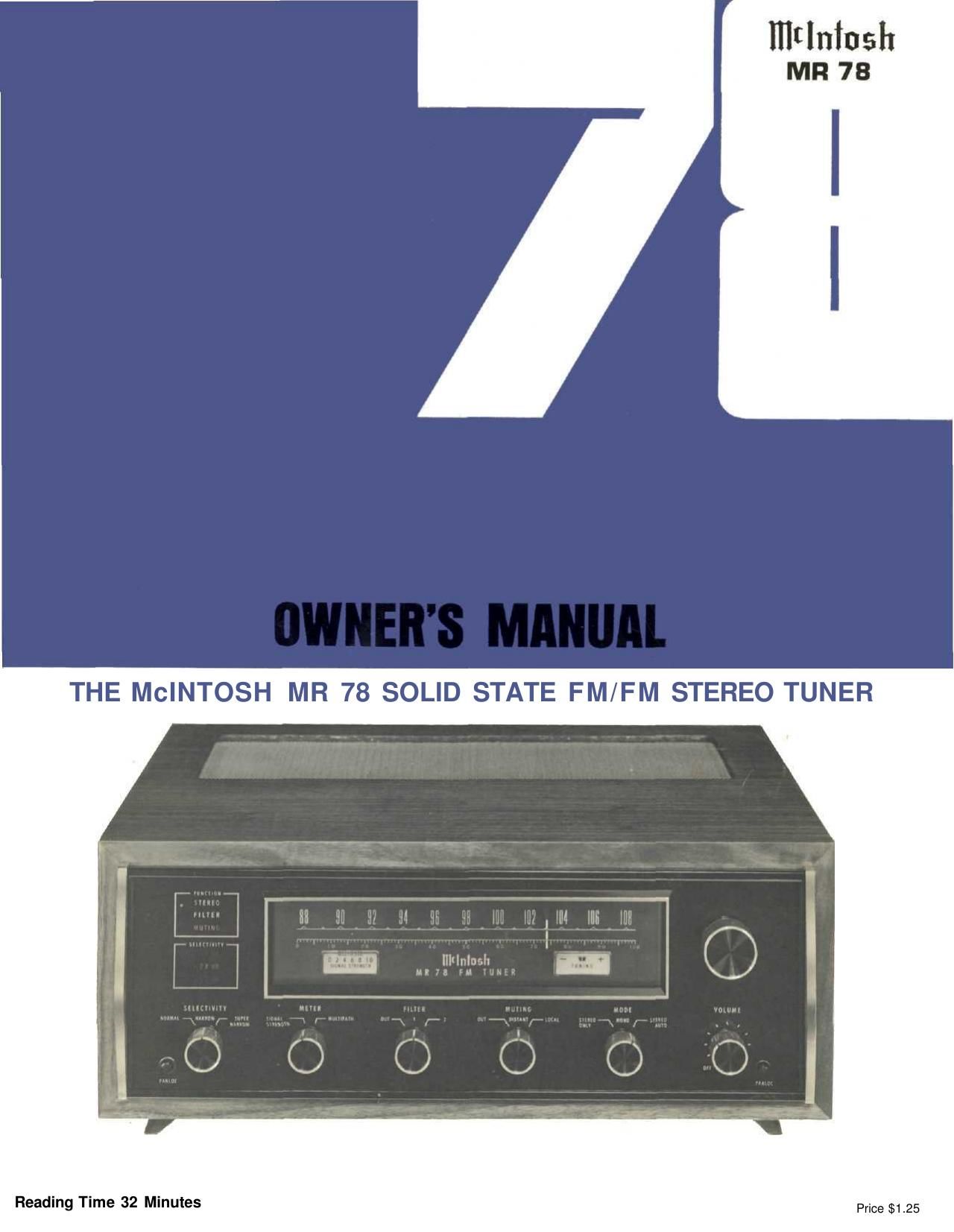
McIntosh MR 78 Owners Manual

Extracted text from McIntosh MR 78 Owners Manual (Ocr-read)


Page 1

Page 2

Your MR 78 FM/FM Stereo Tuner will give you many years of pleasant and satisfactory performance. If you have any questions concerning the operation or maintenance of this instrument, please contact: CUSTOMER SERVICE Mclntosh Laboratory Inc. 2 Chambers Street Binghamton, New York 13903 Phone: 607-723-3512 Take Advantage of 3 years of FREE Factory Service . . . Fill in the Application NOW. CONTENTS GUARANTEE 1 INSTALLATION 2,3 HOW TO CONNECT 4,5 BACK PANEL INFORMATION 6 FRONT PANEL INFORMATION 6,7 LISTENING TO THE MR 78 TUNER 8 PERFORMANCE LIMITS 9 TYPICAL PERFORMANCE CHARTS 10,11 TECHNICAL DESCRIPTION 12,13,14 BLOCK DIAGRAM 15,16 Mclntosh Laboratory Incorporated guarantees this Instrument to be capable of performance as adver- tised. We also guarantee the mechanical and elec- trical workmanship and components to be free of defects for a period of 90 days from date of pur- chase. If such defects occur, Mclntosh Laboratory GUARANTEE or one of its authorized agencies will repair the defect at no cost to the purchaser. This guarantee does not extend to components damaged by im- proper use nor does it extend to transportation to and from the factory or service agency. THREE YEAR FACTORY SERVICE CONTRACT An application for a FREE THREE YEAR FACTORY SERVICE CONTRACT is included with this manual. The terms of the contract are: 1. Mclntosh will provide all parts, materials and labor needed to return the measured performance of the instrument to the original performance limits free of any charge. The SERVICE CON- TRACT does not cover any shipping costs to and from the authorized service agency or the factory. 2. Any Mclntosh authorized service agency will re- pair all Mclntosh instruments at normal service rates. To receive the free service under the terms of the SERVICE CONTRACT, the SERVICE CON- TRACT CERTIFICATE must accompany the instru- ment when taken to the service agency. 3. Always have service done by a Mclntosh author- ized service agency. If the instrument is modified or damaged, as a result of unauthorized repair the SERVICE CONTRACT will be cancelled. Damage by improper use or mishandling is not covered by the SERVICE CONTRACT. 4. The SERVICE CONTRACT is issued to you as the original purchaser. To protect you from misrepre- sentation this contract cannot be transferred to a second owner. 5. The SERVICE CONTRACT is given to purchasers who live In the 50 United States or Canada only. 6. For your protection Mclntosh selects Its dealers carefully. Only one dealer in ten qualifies for a Mclntosh franchise. To receive the SERVICE CONTRACT your purchase must be made from a Mclntosh franchised dealer. 7. Your completely filled in application for a SERV- ICE CONTRACT must be postmarked within 30 days of the date of purchase of the instrument. 8. To receive the SERVICE CONTRACT all informa- tion on the application must be filled in. The SERVICE CONTRACT will be issued when the completely filled in application is received at Mclntosh Laboratory Incorporated In Binghamton, New York. If the application is not received at Mclntosh Laboratory, only the service offered under the 90-day guarantee will apply. Copyright © 1972 By Mclntosh Laboratory Inc. 1

Page 13

Technical Description TUNING MECHANISM AND DIAL DRIVE In the MR 78, the unique design and careful manu- facture of the mechanical dial drive assembly gives smooth flywheel tuning. By controlling the relationship of mass and mechan- ical resistance, and by dividing the workloads in the dial drive system, it becomes nearly impossible to detect any backlash. Yet, the entire dial drive is a model of mechanical stability. For added ease and increased tuning accuracy, a section of the dial pointer is illuminated. FRONT END FM signals enter the tuner through the antenna ter- minals. A coaxial cable conducts the signal to the RF amplifier. In the amplifier the stations are separated, amplified, and converted to a common 10.7 MHz IF frequency. Instead of using a conventional easily overloaded transistor or FET as a straight RF ampli- fier, the MR 78 uses a rugged Junction Field Effect Transistor as an impedance converter to drive a 5-watt power transistor. This combination (a cascode cir- cuit) makes the RF amplifier virtually impossible to overload or cross-modulate. As an example, if you are tuned to a 3 microvolt signal at 96.3 MHz, the MR 78 will reject signals elsewhere on the dial which are at least 4,000,000 times stronger. Thus, a 12 volt signal received at 104.3 MHz would not bother the signal at 96.3 MHz. When tuned to 104.3 MHz, the tuner will not overload. All MR 78 tuners must pass the 12 volt overload test. The MR 78 has an antenna matching circuit in the RF input. In fringe areas a broad low-loss RF circuit provides maximum sensitivity for a low-gain antenna. In metropolitan areas crowded with many strong sig- nals, a sharp RF input circuit greatly reduces spurious responses and achieves maximum sensitivity when connected to a high-gain antenna. The RF bandpass of the antenna matching circuit can be modified by switching the resonator L1 C1 in or out of the circuit. Broad band pass is obtained by set- ting the ANTENNA MATCHING switch to the LOW GAIN ANT. position. This connects+24 volts to the cir- cuit turning diode D1 off and diodes D2, D3 on. In this configuration the antenna is connected directly to the RF amplifier input resonator L2 C2. Diode D3 is tapped on L2 to yield optimum noise, while D2 shorts reson- ator L1 C1 so its loss is not coupled into the circuit. Sharp bandpass is obtained by setting the ANTENNA MATCHING switch to the HIGH GAIN ANT. position. This connects -12 volts to the circuit, turning diode D1 on and diodes D2, D3 off. The RF input circuit becomes a double tuned filter with high Q in both resonators, which provides sharp bandpass. Diode D1 is tapped on L1 to yield optimum selectivity. The oscill- ograph below shows the two bandpass curves of the RF input circuit. 12

Page 17