McIntosh MC 7270 Service Manual

This is the 31 pages manual for McIntosh MC 7270 Service Manual.
Read or download the pdf for free. If you want to contribute, please upload pdfs to audioservicemanuals.wetransfer.com.

Page: 1 / 31
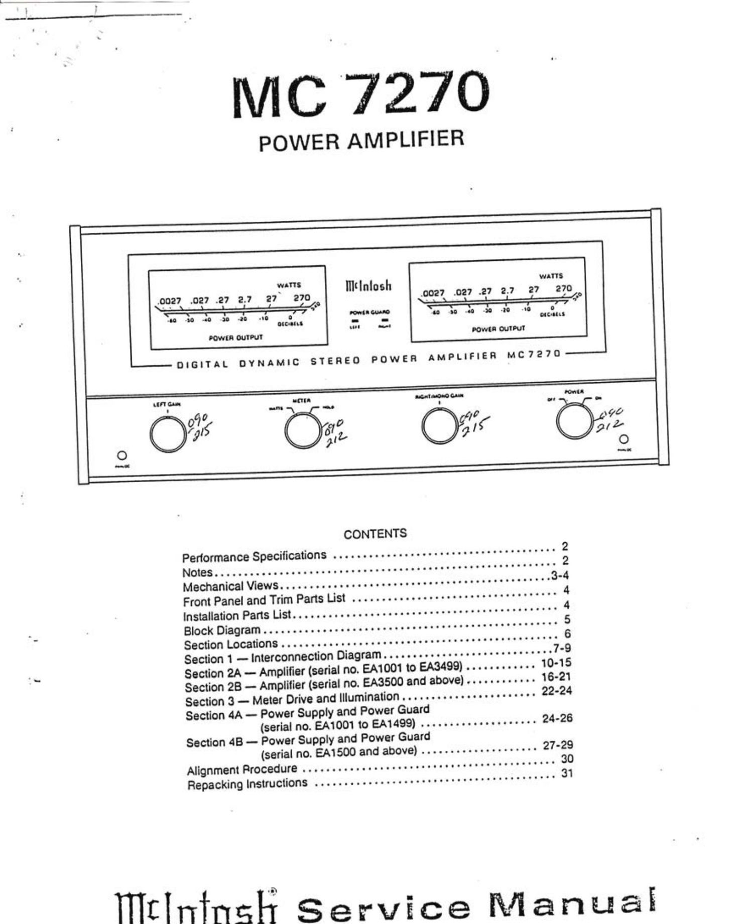
McIntosh MC 7270 Service Manual

Extracted text from McIntosh MC 7270 Service Manual (Ocr-read)


Page 1

MC 7270

POWER AMPLIFIER

11$
1 milnlosh "
.0027 V027 .27 2.7 27 270 .0027 .027 .27 2.7 27 270
\- - \ 1 L 1 l 11'; \- a 3 3 I l . . _' {,0
me an 40 an .3. J. T'W: 0 an a. -8 >1. «0 at.
ore-nu w. M
Down outmv vowel! an»!

LU'I GI- K'III uumouoa- ml:
09,? null '\ 0 p l [o I! o- 90
/
OI OW
O 0
CONTENTS
Pedormance Specifications ...................................... 2
Notes .......................................................... 2
Mechanical Views .............................................. 3-4
Front Panel and Trim Parts List ................................... 4
Installation Parts List ............................................. 4
Block Diagram .................................................. 5
Section Locations ............................................... 6
Section 1 -- Interconnection Diagram ............................. 7-9
Section 2A - Amplifier (serial no. EM 001 to £43499) ............ 10-15
Section 28 - Amplilier (serial no. EASSOO and above) ............ 16-21
Section 3 - Meter Drive and Illumination ............. . . . . ...... 22-24
Section 4A -- Power Supply and Power Guard
(serial no. EA1001 to EA1499) .................... 24-26
Section AB - Power Supply and Power Guard
(serial no. EM 500 and above) .................... 27-29
Alignment Procedure ........................................... 30
Repacking Instructions ......................................... 31

mflningfi Service Manuai

Page 2

3'3

_ erformance
Specifications

POWER OUTPUT
STEREO
270 watts minimum sine wave continuous average
power output per channel. both channels operating into 1
ohm. 2 ohms. 4 ohms. or 8 ohms load impedance. which is:
164 volts RMS across 1 ohm
232 volts RMS across 2 ohms
329 volts RMS across 4 ohms
46.5 volts RMS across 8 ohms

MONO-BRIDGE

540 watts minimum sine wave continuous average
power Output into 2 ohms. 4 ohms. 8 ohms. or 1 6 ohms load
impedance. which is:

32.9 volts RMS across 2 ohms

46.5 volts RMS across 4 ohms

65.7 volts RMS across 8 ohms

93.0 volts RMS across 16 ohms

OUTPUT LOAD IMPEDANCE
STEREO

1 ohm. 2 ohms. 4 ohms. and 8 ohms; separate terminals
are pr0vided tor each output

MONO-BRIDGED -
2 ohms. 4 ohms. 8 ohms. or 16 ohms. balanced to ground.

RATED POWER BAND
20 Hz to 20.000 Hz

TOTAL HARMONIC DISTORTION
STEREO

0.02% maximum harmonic distortion at any power level
from 250 milliwatts to 270 watts per channel Irorn 20 Hz to
20.000 Hz. both channels operating.

MONO
0.02% maximum harmonic distortion at any power level
from 250 milllwatts to 540 watts Irom 20 Hz to 20.000 Hz.

Notes

1. Unless otherwise noted. all voltages indicated on the
lollowing schematics are measured-under the lollowing
conditions:

a AC input at 120 volts. 50/60Hz.

b. All voltages are 110% with respect to ground. A high
impedance (10 megohm) voltmeter must be used.

c. Front panel controls set at

POWER ................................... ON
d. Rear panel controls set at:

MODE ............................... STEREO

INPUT LEVEL ............................. 2.5V

INTERMODULATION DISTORTION
STEREO

0.02% maximum iI instantaneous peak power output is
600 watts or less per channel with both channels operating
tor any combination oI Irequencies. 20 Hz to 20.000 Hz. (

MONO

0.02% maximum lI instantaneous peak power output Is
600 watts or less for any combination oI Irequencies. 20 Hz
to 20.000 Hz.

FREQUENCY RESPONSE (AT ONE WATT OUTPUT)
20 Hz to 20.000 Hz +0 - 0.25 dB.
10 Hzto100.000Hz+O-2d8.

Rafings

DAMPING FACTOR
Greater than 30

INPUT IMPEDANCE
20.000 ohms.

INPUT SENSITIVITY
Switchable: 0.75 volt or 2.5 volts-level control provided
for higher input voltages.

POWER GUARD
Clipping is prevented and THD does not exceed 2% with
up to 20 d8 overdrive a 1 kHz. ~ (

General Information

SEMICONDUCTOR COMPLEMENT
79 silicon transistors
31 silicon rectiliers and diodes
7 Integrated circuit

WEIGHT
82 pounds (37.2 kg) net. 98 pounds (43.5 kg) in shipping
canon.

e. The voltages enclosed in a box (Sections 2 and 3) are
signal voltages that are measured with 3 2.5V. 1I signal connected to both channels at the INPUT
jacks.

2. The heavy lines on the schematics denote the primary
signal paths.

3. Unless otherwise specified:
a. Resistor values are in ohms. ' l
b. Capacitor values smaller than 1 are microlarads (,uF),
and capacitor values greater than 1 are in pi colarads

(9F)-

c. Inductor values are in microhenries 01H).