McIntosh MA 230 Service Manual

This is the 43 pages manual for McIntosh MA 230 Service Manual.
Read or download the pdf for free. If you want to contribute, please upload pdfs to audioservicemanuals.wetransfer.com.

Page: 1 / 43
McIntosh MA 230 Service Manual

Extracted text from McIntosh MA 230 Service Manual (Ocr-read)


Page 1

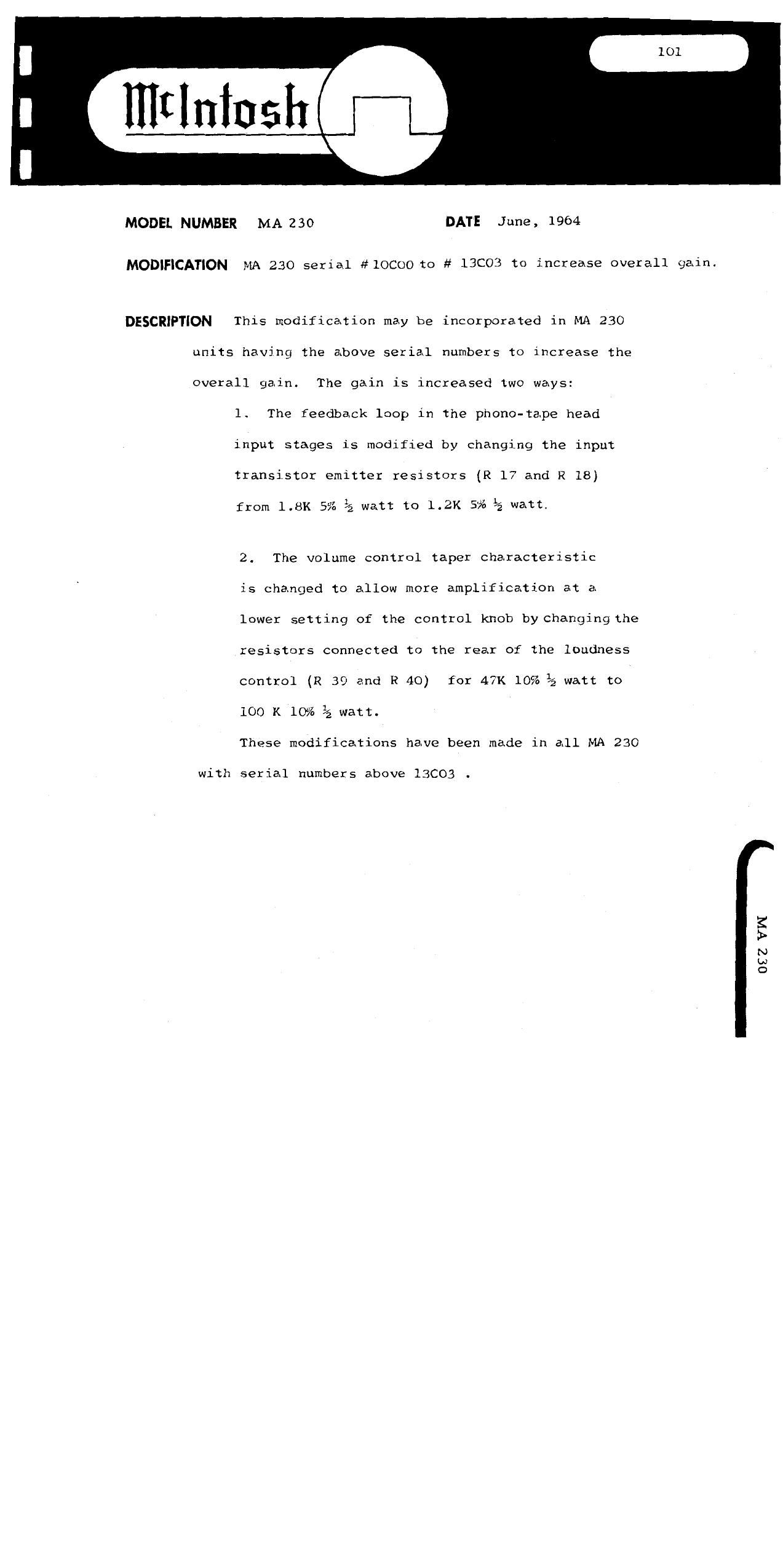
MODEL NUMBER MA 230 DATE June, 1964

MODIFICATION MA 230 serial #lOCOO to # 13C03 to increase overall gain.

DESCRWTKJN This modification may be incorporated in MA 230
units having the above serial numbers to increase the
overall gain. The gain is increased two ways:

1. The feedback loop in the phone-tape head
input stages is modified by changing the input
transistor emitter resistors (R 17 and R 18)

from 1.8K 5% % watt to 1.2K 5% % watt

2. The volume control taper characteristic

is changed to allow more amplification at a
lower setting of the control knob by changingthe
resistors connected to the rear of the loudness
control (R 39 and R 40) for 47K 10% % watt to
100 K 10% g watt.

These modifications have been made in all MA 230

with serial numbers above 13C03 -

0E2 VFW

Page 2

MODEL NUMBER MA 230 DATE June, 1964

MODIFICATION MA 230 serial # lOCOO to # 17C50 to decrease hum

introduced when ELF. filter switch is depressed.

DESCRIPTION This modification may be incorporated in MA 230
units with the above serial number to decrease hum
introduced when the H.F. filter switch is depressed
The hum introduced comes from a 120 cycle ripple component
on the filament supply coupling to the input grids
of the 12AX7 tube. This coupling is eliminated by
adding two resistors to balance the filament supply
with respect to ground. The pilot lamp is rewired
as a part of the modification.

These modiciation have been made in all MA 230's
with serial numbers above 17CSO .

PROCEDURE 1. Remove bare wire from pilot light socket to ground.

2. Remove bare wire from pin 7 of V1 to gr0und<
3. Install new Wire to pilot light and two

100 ohm 10% 1/2 watt resistors as shown below:

POWER TRANS


was gonna;
V- TO on u L
Mow-a (new) REMOVED

IMWN Ill.)


'4
g T-l33CIOI
1

* a: mom LAMP TD
mOUND L". meb

BROWN WIRE ADDED

BOTH (3011 RESISTOR:
ARE CONNECTED TO

unusr TUB: GRND
LAMP

OEZ VW

Page 10

MODEL NUMBER: MA 230 DATE: MARCH 1965
MODIFICATION: Tightening the transformer mounting screws to eliminate buzzing.

DESCRIPTION: The top and bottom transformer laminations will vibrate when they are not secured
by the impregnating varnish or clamped by the transformer end-bells, Some MA

230s transformers have the problem.

PROCEDURE: Tightening the transformer mounting screws may secure the laminations enough
to eliminate the buzz. If this fails thin shims should be inserted between the lami-
nations and the end bells.

TO INSERT THE SHIMS:

i. Loosen the transformer mounting screws.

2. Insert two shims under each end-bell. Make the shims from metal or fiber. The
shims should be 3 x 1/2 x 1/16".

3. Re-tighten the mounting.

083 VW

Page 24

MC-2505-l

MCF2505 SOLID STATE AMPLIFIER Page -1-

Servicing the McIntosh MC~2505 solid state amplifier is easy.
Transistor and tube type amplifiers have much in common. It is
necessary to learn only a few basic principles.

1. Being a solid state amplifier, the circuits are in
operation the moment the instrument is turned on.
It is important to be certain that all circuits are
operating properly before applying full line voltage.
If some circuits are not operating properly, it is
possible to damage additional circuit components.
Therefore, when a McIntosh MC-2505 comes in for
service, NEVER JUST PLUG IT IN AND TURN IT ON.
Turn the MC-2505 on/off switch on, but turn the
speaker switch off. Always use a Variac or Power-
stat. Plug the amplifier into the Variac, but set
the Variac output to zero volts. Bring the line
voltage to the amplifier up very slowly. As you do
so, monitor the output voltage on each channel.
This is done with a VTVM. Connect the VTVM common
lead to the chassis and the probe to the point shown:

__.-...J

:§E---~~ .atifi.
\m at»;

Ipuri-n . f: . I

POWER OUTPUT PRINTED CIRCUIT BOARD

Set the VTVM on about a 15 volt positive DC scale.

Set the needle of the VTVM to the center of the scale
rather than to zero. As the line voltage to the amplifier
is slowly increased, the VTVM needle will swing positive

a few volts, then back past the center position, then
slightly negative, then return to center position. This
complete cycle will occur before the line voltage to the

Page 26

MC-2505-1

Page -3-

4. Regardless of the incorrect indication, it is usually
not difficult to find the source of trouble. Turn the
line voltage completely off. Discharge the large filter
capacitors. Do not discharge the capacitors by shorting
them directly to the chassis. Because of the arcing that
will occur, the chassis will be marred. The proper way
to discharge these capacitors is with a resistor. Use a
resistor of at least a two watt rating whose value is
approximately 5 to 15 ohms. Hold it across each of the
large filters. In this way the power supply will be
safely discharged. Failure to discharge the power
supply before working on the amplifier could cause
several transistors to be destroyed.

5. After the power supply is discharged, check each tran-
sistor. This is done quite easily with the VTVM.
CAUTION: USE VTVM SUCH AS THE RCA SENIOR VOLTOHMYST.
Do not use older 1,000 ohms per volt VOM. This type
of instrument may destroy the transistor by introducing
excessive current into the transistor. Set the VTVM
to measure ohms; after the power supply is discharged,
check each transistor. Set the VTVM to measure ohms;
use the "R x 1" scale. Measure across each junction
of the transistor. Measure from base to collector,
base to emitter, emitter to collector, emitter to base,
collector to emitter, and collector to base. Also
measure from the case of the transistor to ground, In
no case should there be a direct short. In most cases,
only one channel of the amplifier will be defective.
Therefore, until you become familiar with the readings
to expect in each case, compare the defective channel
with be good channel. Although a defective transistor
will usually be indicated by a direct short, this is
not always the case. It is possible for a difference
of only 2 or 3 ohms to indicate a defective transistor.
For example, if a transistor in the defective channel
reads 12 ohms from one junction to another, and the
similar transistor in the good channel reads 10 ohms,
the transistor which reads 12 ohms is probably defective.