McIntosh C20 Brochure

This is the 2 pages manual for McIntosh C20 Brochure.
Read or download the pdf for free. If you want to contribute, please upload pdfs to audioservicemanuals.wetransfer.com.

Page: 1 / 2
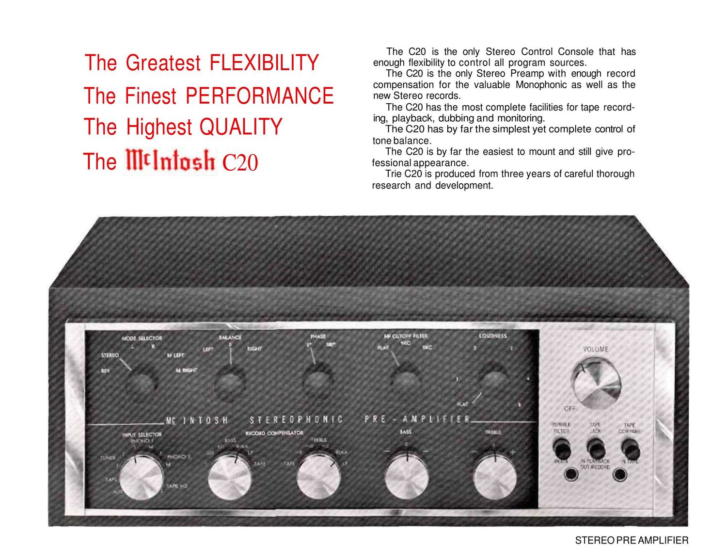
McIntosh C20 Brochure

Extracted text from McIntosh C20 Brochure (Ocr-read)


Page 1

LABORATORY, INC. 2 CHAMBERS STREET, BINGHAMTON. N. Y, Phone-Area Code 607-723-5491 2O-HP30-761 Printed In U.S.A. BE012003 In Canada: Manufactured under license by: McCurdy Radio Industries, Ltd., 22 Front Street West, Toronto, Canada Input Selector: Selects any one eight pro- gram sources including Tape, Tuner 1 and Tuner 2, Auxiliary, Phono 1 and Phono 2, Tape Head 1 and Tape Head 2. Each phono input has two switch positions, one for stereo the other paralles the stereo car- trige for Monophonic records. Mode Selector: Reverse: connects left channel to right speaker, right channel to left speaker, corrects for left-right reversal of program. Stereo: (normal Stereo mode selector posi- tion) left channel to left speaker, right channel to right speaker. Left: left channel to left speaker no pro- gram to right speaker. Right: right channel to right speaker, no program to left speaker. M Left: left channel only to both speakers. M Right: right channel only to both speakers. Record Compensator: Separate bass and treble compensator switches including "RIAA," "LP," "Tape-Head," flat position for microphone and other positions for monophonic records. (Turning "TREBLE" control to "TAPE" gives flat response. Turning "BASS" to "O" gives flat response.) Tone Controls: Treble: boost 13 db at 20,000 cycles atten- uate 18 db at 20,000 cycles. Bass: boost 16 db at 20 cycles, attenuate. 20 db at 20 cycles. Balance Control: To balance for unequal pro- gram source: Turning control to left re- duces right channel to No Output Turning control to right reduces left channel to No Output. Phase Control: Reverses phase in the left channel to correct for speaker or program phasing. HF Cutoff Filter: Three positions providing (1) no filter action for normal use, (2) 9 KC cutoff, and (3) 6 KC cutoff to sucpress record noise and hiss. Loudness Control: Compensates for the Flet- cher-Munson hearing characteristics as program loudness is reduced. Rumble Filter: Suppress low frequency dis- turbences such as rumble. Tape: Front panel jacks, push button switch controlled to permit the addition of a port- able tape recorder without disrupting the equipment permanently installed. Tape Monitor: To permit instantaneous mon- itoring of tape before and alter recording. Low Frequency Trim Controls: On the back panel. Compensate for unequal response at low frequencies due to position of speak- ers or differences in speaker efficiency. Provides 6 db boost at 50 cycles starting from 500 cycles or 8 db cut at 20 cycles starting from 200 cycles. CONTROLS Main Output: 2.5V with rated input 2 output jacks in parallel for each channel Tape Output: 0.25V with rated input 1 output jack for each channel Left plus right output: 2.5 volts from source impedance of 23.000 ohms Voltage Amplification: Low level inputs to Main Output: 1,000 to 1 (60db) at 1000 cycles Low level inputs to Tape Output: 100 to 1 (40db) at 1000 cycles High level inputs to Main Output: 10 to 1 (20db) High level inputs to Tape Output: 1 to 1 (0db) Tape Monitor input to Main Output: 10 to 1 (20db) A.C. Aux. Outlets: 1 unswitched for tape machine or turntable. colored Red; 4 switched, colored Black Power Requirements: 117 volts 60 cycles A.C. 35 watts MECHANICAL SPECIFICATIONS Size: 155/8" wide by 51/8" high. Overall depth of chassis behind front panel is 1213/16".. The space required in front of cabinet panel for the thickness of the panel and knobs is 1¼". Weight: Chassis only 18 pounds. In ship- ping carton 28½ pounds. ELECTRICAL SPECIFICATIONS Frequency Response: ±0.5 db 20 to 20,000 cycles Distortion: Less than 0.2% at rated output, 20 to 20,000 cycles Hum and Noise: High level inputs: 85 db below rated output Low level inputs: less than 2 microvolts et input terminals Input Sensitivity and Input Impedance: Auxiliary; 0,25 volts 470.000 ohms Tape: 0.25 volts 470,000 ohms Tuner 1: 0.25 volts 470,000 ohms Tuner 2: 0,25 volts 470,000 ohms Phono 1: 2 to 10 millivolts 47,000 ohms for low output cartridge 10 to 70 millivolts 47,000 ohms for hi output cartridge 0.1 volt 220 mmf in series with 47,000 ohms for Xtal or Ceramic Phono 2: Same as phono 1 Tape Head 1: 2 to 10 millivolts 47,000 ohms for low output head Tape Head 2; Same as tape head 1 Tape Compare (Monitor): 0.25 volts, 115,000 ohms