Mackie 8bus schematic 23F 2
This is the 1 pages manual for mackie 8bus schematic 23F 2.
Read or download the pdf for free. If you want to contribute, please upload pdfs to audioservicemanuals.wetransfer.com.
Extracted text from mackie 8bus schematic 23F 2 (Ocr-read)
Page 1
mmgo 8-BUS SERVICE MANUAL
M 862/ M 824/ M B'l6/ M B-E
8'BUS M ETER BRIDGES
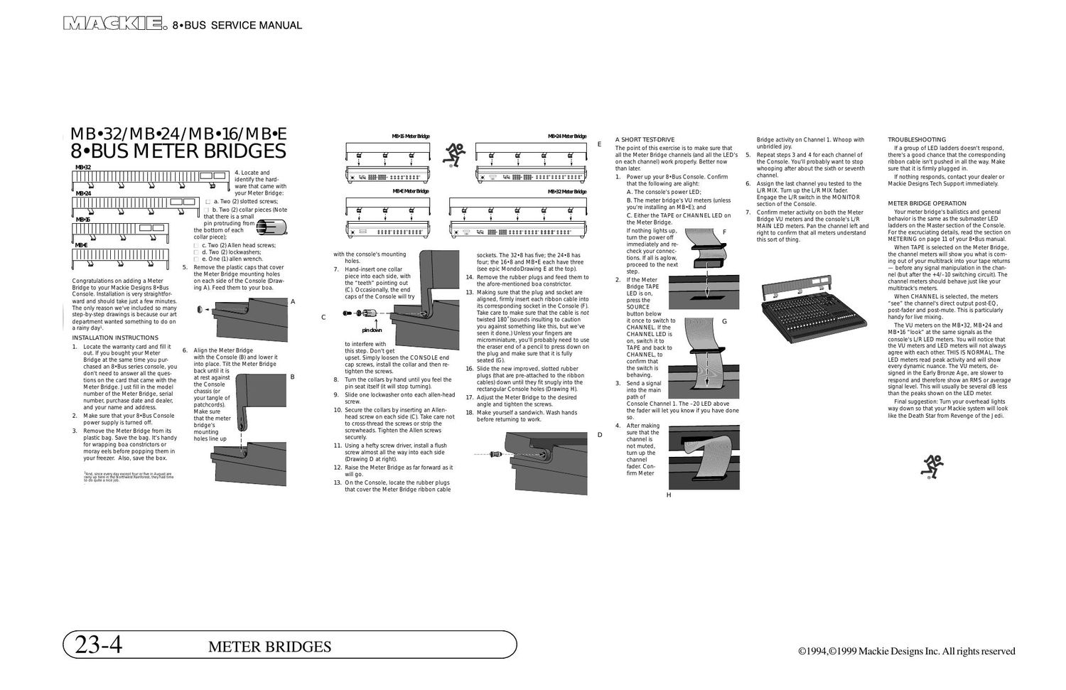
4. Locate and
identify the hard-
ware that came with
your M eter Bridge:
Congratulations on adding a Meter
Bridge to your Mackie Designs B'Bus
Console. Installation is very straig htfor-
ward and should take just a few minutes.
The only reason We've included so many
step-by-step draWings is because our art
department wanted something to do on
a rainy day.
INSTALLATION INSTRUCTIONS
1. Locate the warranty card and fill it
out. If you bought your M eter
Bridge at the same time you pur-
chased an B-Bus series console. you
don't need to answer all the ques-
tions on the card that came with the
M eter Bridge. I ust fill in the model
number of the M eter Bridge, serial
number. purchase date and dealer.
and yourname and address.
2. M ake sure that your B-Bus Console
power supply is turned off.
3. Remove the Meter Bridge from its
plastic bag. Save the bag. It's handy
for wrapping boa constrictors or
moray eels before popping them in
yourfreezer, Also, save the box.
)And.smceevewdaryextevuourorhve inAu ustaie
my; me in: e nnhwest Rainfmest. they ad time
to oauxteamtEiob
|:||:| a. Two (2lslotted screws;
I 9 b. Two (2) collar pieces (N ote
that there is a small
pin protruding from
the bottom of each
collar piece):
C. Two (2)Allen head screws;
d. Two (2) lockwashers.
e. One (1) allen wrench.
Remove the plastic caps that cover
the Meter Bridge mounting holes
on each side of the Console (Draw-
ing A). Feed them to your boa
3
Align the Meter Bridge
with the Console (B) and lower it
into place. Tilt the Meter Bridge
back until it is
at rest against
the Console
chassis (or
yourtangle of
patchcords),
M ake sure
that the meter
bridge's
mounting
holes line up
with the console's mounting
7.
10.
11.
12.
ll
holes.
Hand-insert one collar
piece into each side. With
the "teeth" pointing out
(CI Occasionally. the end
caps of the Console will try
to interfere With
this step. Don't get
upset. Simply loosen the C0 N S0 LE end
cap screWs. install the collar and then re-
tighten the screws.
Turn the collars by hand until you feel the
pin seat itself (it Will stop turning).
Slide one lockWasheronto each alien-head 17_
screw.
Secure the collars by inserting an Allen- 13
head screw on each side (C). Take care not
to cross-thread the screws or strip the
screwheads. Tighten the Allen screws
securely.
Using a hefty screw driver. install a flush
screw almost all the Way into each side
(Drawing D at right).
Raise the Meter Bridge as far forward as it
will go.
0 n the Console. locate the rubber plugs
that cover the Meter Bridge ribbon cable
14.
16.
sockets. The 32-8 has five: the 2403 has
four: the 16-8 and MB'E each have three
(see epic MondoDrawmg E at the top).
Remove the rubber plugs and feed them to
the afore-mentioned boa constrictor.
. Making sure that the plug and socket are
aligned, firmly insert each ribbon cable into
its corresponding socket in the Console (F).
Take care to make sure that the cable is not
twisted 180"(sounds insulting to caution
you against something like this, but we've
seen it done.) Unless your fingers are
microminiature, you'll probably need to use
the eraserend ofa pencil to press down on
the plug and make sure that it is fully
seated (G).
Slide the new improved. slotted rubber
plugs (that are pre-attached to the ribbon
cables) down until they fit snugly into the
rectangular Console holes (Drawing H).
Ad)ust the Meter Bridge to the desired
angle and tighten the screws.
. Make yourselfa sandwich. Wash hands
before returning to Work.
(23-4
METER BRIDGES
A SHORT TEST-DRIVE
The point of this exercise is to make sure that
all the Meter Bridge channels (and all the LEDs
on each channel) work properly. Better now
than later.
1. Power up your B-Bus Console. Confirm
that the following are alight
A. The consoles power LED.
B. The meter bridgesVU meters (unless
youre installing an MB'E): and
C. Eitherthe TAPE orCHANNEL LED on
the M eter Bridge.
WWII
If nothing lights up.
turn the power off
immediately and re-
check your connec-
tions. If all is aglow,
proceed to the next
step.
2. Ifthe Meter [
Bridge TAPE
LED is on. I]
press the
SOURCE
button below
it once to switch to
CHANNEL. If the
CHANNEL LED is
on. switch it to
TA PE and back to
C HAN N EL, to
confirm that
the sWitch is
behaving.
3. Send a signal
into the main
path of
Console Channel 1. The -20 LED above
the faderWill let you know if you have done
so.
4. After making
sure that the
channel is
not muted.
turn up the
channel
fader. Con-
firm M eter
G
5.
Bridge activity on Channel 1. Whoop with
unbridled joy.
Repeat steps 3 and 4 for each channel of
the Console. You'll probably want to stop
whooping after about the sixth or seventh
channeL
Assign the last channel you tested to the
(JR MIX. Turn up the UK MIX fader.
Engage the L/R switch in the M O N ITO R
section of the Console.
Confirm meter activity on both the M eter
Bridge VU meters and the console's L/R
MAIN LED meters. Pan the channel left and
right to confirm that all meters understand
this sort of thing.
TROUBLESHOOTING
If a group of LED ladders doesn't respond,
there's a good chance that the corresponding
ribbon cable isn't pushed in all the Way. Make
sure that it is firmly plugged in
If nothing responds. contact your dealer or
M ackie Designs Tech Support immediately.
METER BRIDGE OPERATION
Your meter bridge's ballistics and general
behavior is the same as the sub master LED
ladders on the Master section of the Console,
Forthe excruciating details. read the section on
METERING on page 11 of yourB-Bus manual.
When TAPE is selected on the M eter Bridge,
the channel meters will show you what is co m-
ing out of your multitrack into your tape retums
- before any signal manipulation in the chan-
nel (but afterthe +4/-10 sWitching circuit). The
channel meters should behave )ust like your
multitrack's meters
When CHAN N EL is selected. the meters
see" the channels direct output post-E0.
post-fader and post-mute. This is particularly
handyfor live mixing.
The VU meters on the M B'32. MB-24 and
MB-16 look at the same signals as the
console's UR LED meters. You will notice that
the VU meters and LED meters will not always
agree with each other. THIS IS NORMAL. The
LED meters read peak activity and will show
every dynamic nuance. The VU meters. de-
signed in the Early Bronze Age, are slower to
respond and therefore show an RMS oraverage
signal level. This Will usually be several dB less
than the peaks shown on the LED meter.
Final suggestion: Turn your overhead lights
way down so that your M ackie system will look
like the Death Star from Revenge of the J edi.
© 1994,© 1999 Mackie Designs Inc. All rights reserved