Luxman r 341 service manual

This is the 56 pages manual for luxman r 341 service manual.
Read or download the pdf for free. If you want to contribute, please upload pdfs to audioservicemanuals.wetransfer.com.

Page: 1 / 56
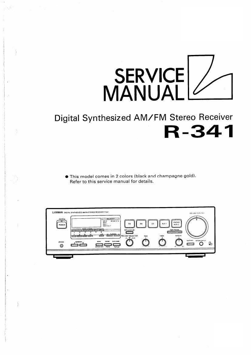
luxman r 341 service manual

Extracted text from luxman r 341 service manual (Ocr-read)


Page 2

R-341

Contents
Specifications ................................................................................................................................... 8 to 4
Connection Guidelines .................................................................................................................................. .. 5 to 6
Controls and Switches .................................................................................................................................................... 7 to 12
Jacks and Terminals ................................................................................ 13 to 15
Operation Guidelines .................................................................................................................................................... 1610 20
Disassembly Instruction ................................................................................................................................................ 21 to 22
Adjustment Procedures .................................................... 23 to 25
Adjustment Locations ................................................................................................................ 27 to 28
Adjustment Locations ...................................................................................................................... 29 to 30
Block Diagram ....................................................................................................................... . 31 to 32
Parts-Layout on P.C. Boards and Wiring Diagram .................................................................... 33 to 36
Parts-Layout on P.C, Boards and Wiring Diagram .......................................................................... 37 to 40
Schematic Diagram ...................................................................................................................................................... 41 to 51
Electrical Parts List ...................................................................................................................................................... 52 to 61
Peaking Assembly Parts List .. ......................................................................... 62
Packing Method View ........................................................................................................................................................... 62
Cabinet Assembly Parts List ................................................................................................................................................. 63
Exploded View (Cabinet) . .............................................. 64 to 66
Semi-Conductor Lead Identifications ......................................... ; .................................................................................. 67 to 71

Spare Schematic Diagram Inserted.