Luxman MQ 68 C Service Manual

This is the 6 pages manual for Luxman MQ 68 C Service Manual.
Read or download the pdf for free. If you want to contribute, please upload pdfs to audioservicemanuals.wetransfer.com.

Page: 1 / 6
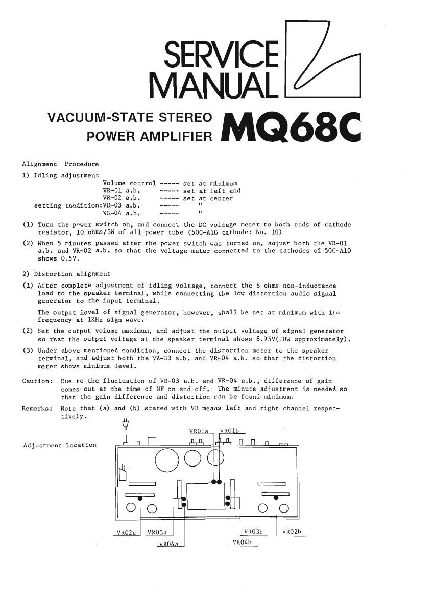
Luxman MQ 68 C Service Manual

Extracted text from Luxman MQ 68 C Service Manual (Ocr-read)


Page 1

SERVICE
MANUAL

VACUUM-STATE STEREO MQ68C
POWER AMPLIFIER

Alignment Procedure
1) Idling adjustment

Volume control - set at minimum

VR-Ol a.b. set at left end

VR-OZ a.b. set at center
setting condition1VR-O3 a.b. "

VR-04 a.b. "

(1) Turn the power switch on, and connect the DC voltage meter to both ends of cathode
resistor, 10 ohms/3w of all power tube (SOC-A10 cathode: No. 10)

(2) when 5 minutes passed after the power switch was turned on, adjust both the VR-Ol
a.b. and VR-OZ a.b. so that the voltage meter connected to the cathodes of SOC-A10
shows 0.5V.

2) Distortion alignment

(1) After complete adjustment of idling voltage, connect the 8 ohms non-inductance
load to the speaker terminal, while connecting the low distortion audio signal
generator to the input terminal.

The output level of signal generator, however, shall be set at minimum with its
frequency at lKHz sign wave.

(2) Set the output volume maximum, and adjust the output voltage of signal generator
so that the output voltage at the speaker terminal shows 8.95V(10W approximately).

(3) Under above mentioned condition, connect the distortion meter to the speaker
terminal, and adjust both the VR-03 a.b. and VR-OA a.b. so that the distortion
meter shows minimum level.

Caution: Due to the fluctuation of VR-OB a.b. and VR-04 a.b., difference of gain
comes out at the time of NF on and off° The minute adjustment is needed so
that the gain difference and distortion can be found minimum.

Remarks: Note that (a) and (b) stated with VR means left and right channel respec-
tively.

é? VROla VROlb
Adjustment Location U j PETE? r n J] n 111-:
E::::: -___- C:::::3

E::;F:3 E::;::]
00 OO

VROZa VROBa VR03h VROZh
yggga VROéh