Luxman mq 3600 schematic
This is the 5 pages manual for luxman mq 3600 schematic.
Read or download the pdf for free. If you want to contribute, please upload pdfs to audioservicemanuals.wetransfer.com.
Extracted text from luxman mq 3600 schematic (Ocr-read)
Page 1
Lukl/Vl any]
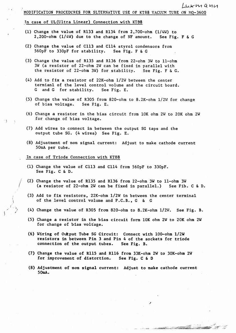
MODIFICATION PROCEDURES FOR SLTERNATIVE USE OF KTSB VACUUM TUBE 0N MQ-36OO
in case of UL(U1tra Linear) Connection with KT88
(1)
(2)
(3)
(4)
(5)
(6)
(7)
(8)
Change the value of R133 and R136 from 2,700-ohm (l/AW) to
2,200-ohm (llhw) due to the change of NF amount. See Fig. F & G
Change the value of C113 and C114 styrol condensers from
560p? to 330pF for stability. See Fig. F 8 G
Change the value of R135 and R136 from 22-ohm 3w to ll-ohm
3W (a resistor of 22-ohm 2W can be fixed in parallel with
the resistor of 22-ohm 3H) for stability. See Fig. F & G.
Add to fix a resistor of 22K-ohm 1/2w between the center
termianl of the level control volume and the circuit board.
G and G for stability. See Fig. E.
Change the value of R305 from 820-ohm to 8.2K-ohm 1/2w for change
of bias voltage. See Fig. E.
Change a resistor in the bias circuit from 10K ohm 2W to 20K ohm 2W
for change of bias voltage.
Add wires to connect in between the output 86 taps and the
output tube SG. (4 wires) See Fig. E.
Adjustment of non signal current:
Adjust to make cathode current
SOmA per tube.
In case of Triode Connection with KT88
(l)
(2)
(3)
(4)
(5)
(6)
(7)
(8)
Change the value of C113 and C114 from 560pF to 330pF.
See Fig. C & D.
Change the value of R135 and R136 from 22-ohm 3W to ll-ohm 3W
(a resistor of ZZ-ohm 2W can be fixed in parallel.) See Fib. C 5 D.
Add to fix resistors, ZZK-ohm 1/2 in between the center terminal
of the level control volume and P.C.B., G & G
Change the value of R305 from BZO-ohm to 8.2K-ohm 1/2W. See Fig. B.
Change a resistor in the bias circuit form 10K ohm 2V to 20K ohm 2W
for change of bias voltage.
Hiring of Output Tube SG Circuit: Connect with lOO-ohm 1/2
resistors in between Pin 3 and Pin a of the sockets for triode
connection of the output tubes. See Fig. 3.
Change the value of R115 and R116 from 33K-ohm 2V to 30K-ohm 2H
for improvement of distortion. See Fig. C 8 D
Adjustment of non signal current: Adjust to make cathode current
SOmA.