Luxman M 150 Owners Manual

This is the 10 pages manual for Luxman M 150 Owners Manual.
Read or download the pdf for free. If you want to contribute, please upload pdfs to audioservicemanuals.wetransfer.com.

Page: 1 / 10
Luxman M 150 Owners Manual

Extracted text from Luxman M 150 Owners Manual (Ocr-read)


Page 1

CONTROLS & CONNECTORS

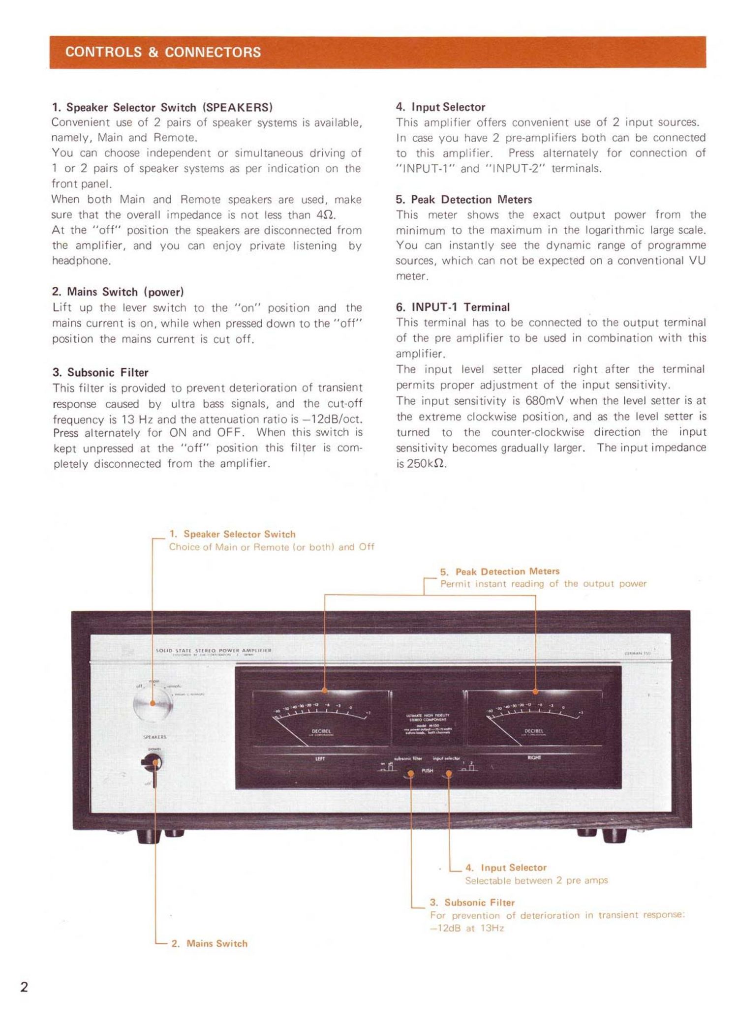
1. Speaker Selector Switch (SPEAKERS)

Convenient use of 2 pairs of speaker systems is available,
namely, Main and Remote.

You can choose independent or simultaneous driving of
l or 2 pairs of speaker systems as per indication on the
front panel.

When both Main and Remote speakers are used, make
sure that the overall impedance is not less than 49.

At the off" position the speakers are disconnected from
the amplifier, and you can enjoy private listening by
headphone.

2. Mains Switch (power)

Lift up the lever switch to the "on" position and the
mains current is on, while when pressed down to the "off"
position the mains current is cut off.

3. Subsonic Filter
This filter is provided to prevent deterioration of transient
response caused by ultra bass signals, and the cut-off

frequency is 13 Hz and the attenuation ratio is --l2dB/oct.
Press alternately for ON and OFF. When this switch is

kept unpressed at the "off" position this filter is com-
pletely disconnected from the amplifier.

1. Speaker Selector Switch

(37,.iil i 'nrii ,~ "ir-iru i. iv. [.iit' girl] 3"

4. Input Selector

This amplifier offers convenient use of 2 input sources.
In case you have 2 pre-amplifiers both can be connected
to this amplifier. Press alternately for connection of
"INPUT-l" and "INPUT-2" terminals.

5. Peak Detection Meters

This meter shows the exact output power from the
minimum to the maximum in the logarithmic large scale.
You can instantly see the dynamic range of programme
sources, which can not be expected on a conventional VU
meter.

6. INPUT~1 Terminal

This terminal has to be connected to the output terminal
of the pre amplifier to be used in combination with this
amplifier.

The input level setter placed right after the terminal
permits proper adjustment of the input sensitivity.

The input sensitivity is 680mV when the level setter is at
the extreme clockwise position, and as the level setter is
turned to the counter-clockwise direction the input

sensitivity becomes gradually larger. The input impedance
is 250KB.

5. Peak Detection Meters

PHI" i i'i»',1 l lrndlllt] iii ill» iiittm' pawer

501! All SUMO 70le AMl'lllilll
. . . .., t V g

2. Mains Swrtch

Input Selector

.wlm .:vlv> !' Imi .i' .l- :i'ii-s

_ 3. Subsonic Filter
F l] (3" i i ? .gii
syntl" .11 'ZH'

-ti lei "l'»lilil 'rtr ~lrr wiw i m"

Page 2

7.8. Input Level Setter The red terminal is for (+) and the black for (-). Be

These knobs are volume controls for adjustment of the careful about phase matching. For further details, refer to

input sensitivity of the lNPUT~l terminal. connection of speakers.

Adjust the input level when the output voltage of the pre

amplifier used in combination is higher than 680mV. (7) 12. Extra Mains Outlet (UNSWITCHED)

is for the right channel, and (8) is for the left channel. Convenient for supply of mains power to other audio

This amplifier is delivered with the volume set at the equipments to be used in combination.

extreme clockwise position, i.e., input sensitivity 680mV. This terminal is independent of the mains switch of the
amplifier.

9. INPUT-2 Terminal The rated capicity is 300W.

Same as INPUT-l Terminal except that the input level

setter is not provided and that the input sensitivity is fixed 13. Mains Line Fuse

at 680mV. A 5A (100-125V) or 2.5A (200-250V) fuse should be

The ihDUt impedance is 250k9. lf YOU have another inserted in the mains power circuit of this amplifier. If

amplifier connect the OUIDUI terminal to this terminal. the fuse blows out, replace it after ascertaining the cause
and applying an appropriate remedy.

10.11. Speaker Terminals Replace the fuse by turning the cap with a (+) driver

The speaker systems should be connected to these terminals. towards the arrow mark.

Press the cap of the terminal and insert the bare speaker Be sure that the mains power cord is desconnected.

cord into the terminal hole, and release it. Now they are

firmly connected. 14. Mains Connector

These terminals are coupled with the speaker switch, and One end of the attached mains cord should be connected

the speaker switch must be set at the position cor- to this point, while the other end with the plug should be

responding to the terminal to which the speaker systems connected to the mains power SUDDIY source-

are connected.
(10) is for the main speaker and (11) is for the remote
speakers.

6. INPUT-1 Terminal

LT ' ilii»'irhiiii . :r» :1", I_!!"i' i"[ii' 9" l'I,-lly

_. --- 9, INPUT-2 Terminal

l.l lrllllk' liiiVI i? [fire FWD ,lrlf, ll'sjplT Itl'NillJll, lx flitErJ
, l
mlltl' idlilw

T 7.8. Input Level Setter

Clari- - i'ln' ll,llllil1 QT pr ,lllll sin-{l axiiuu 'lu; lllljljl lr-w-l

., pantsu'z . i444

.. .l'

. u «.yflcfi

i
.Ll-4< "- . ' -

. -e. ~ ..._ .i. .: n+6 .t.«r.* '._."......-'1n:--r
i g
V

l
mm-II- l fi- .-

m J."
DOW-1i '2 r-Isnfl-l m
. Q Q- Q Q"? ,

Mil-Iran run rum:
'1 r-l-i -'-i r"

r-U
cum . u
-_-__

45 us- we

In.

.

D-

12. Extra Mains Outlets lUnswitchedl J .

' n-ln. mm. a, .n, .ill In _. i Wt... 14. Mains Power Input

t lily-ll 10.11. Speaker Terminals
Main ieaker

13. Mains Line Fuse ,. 8

rel lwr'l . 'l m l wl w '4' M iii» lrrr'vu'ivil 1H"
l W. l : 1' '
Remote Speaker
Hurt henna-aw are lic'nlllvH' ll til-ill Yv-WFlrllrdlK virt

reuhlw? i