Luxman l 2 Owners Manual

This is the 8 pages manual for luxman l 2 Owners Manual.
Read or download the pdf for free. If you want to contribute, please upload pdfs to audioservicemanuals.wetransfer.com.

Page: 1 / 8
luxman l 2 Owners Manual

Extracted text from luxman l 2 Owners Manual (Ocr-read)


Page 1

SWITCHES & TERMINALS

umwmsmwmwwmvvmmewwsmh ms . 1m .. «can . :.:.:.:- .1 . ., -.:

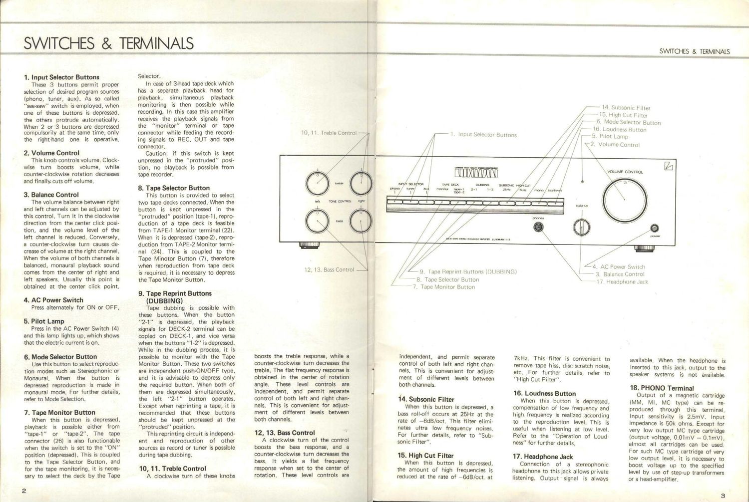
1. Input Selector Buttons

These 3 buttons permit proper
selection of desired program sources
(phono. tuner, aux). As so called
"see-saw" switch is employed, when
one of these buttons is depressed.
the others protrude automatically.

When 2 or 3 buttons are depressed
compUlsorily at the same time, only

the right-hand one is operative.

2. Volume Control

This knob controls volume. Clock-
wise turn boosts volume, while
counter-clockwise rotation decreases
and finally. cuts off volume.

3. Balance Control

The volume balance between right
and left channels can be adjusted by
this control. Turn it in the clockwise
direction from the center click posi-
tion, and the volume level of the
left channel is reduced. Conversely,
a counter-clockwise turn causes de-
crease of volume at the right channel.
When the volume of both channels is
balanced, monaural playback sound
comes from the center of right and
left speakers. Usually this point is
obtained at the center click point.

4. AC Power Switch
Press alternately for ON or OFF.

5. Pilot Lamp

Press in the AC Power Switch (4)
and this lamp lights up,which shows
that the electric current is on.

6. Mode Selector Button

Use this button to select reproduc-
tion modes such as Stereophonic or
Monaural. When the button is
depressed reproduction is made in
monaural mode. For further details,
refer to Mode Selection.

7. Tape Monitor Button

When this button is depressed,
playback is possible either from
"tape-1" or tape-2". The tape
connector (26) is also functionable
when the switch is set to the "ON"
position (depressed). This is coupled
to the Tape Selector Button, and
for the tape monitoring, it is neces-
sary to select the deck by the Tape

2

Selector.

In case of 3-head tape deck which
has a separate playback head for
playback, simultaneous playback
monitoring is then possible while
recording. In this case this amplifier
receives the playback signals from
the monitor" terminal or tape
connector while feeding the record-
ing signals to REC. OUT and tape
connector.

Caution: if this switch is kept
unpressed in the "protruded" posi-
tion, no playback is possible from
tape recorder.

8. Tape Selector Button

This button is provided to select
two tape decks connected. When the
button is kept unpressed in the
protruded" position (tape-1), repro-
duction of a tape deck is feasible
from TAPE-1 Monitor terminal (22).
When it is depressed (tape-2), repro-
duction from TAPE-2 Monitor termi-
nal (24). This is coupled to the
Tape Minotor Button (7). therefore
when reproduction from tape deck
is required, it is necessary to depress
the Tape Monitor Button.

9. Tape Reprint Buttons

(DUBBING)

Tape dubbing is possible with
these buttons. When the button
"2-1" is depressed, the playback
signals for DECK-2 terminal can be
copied on DECK-1, and vice versa
when the buttons "1-2 is depressed.
While in the dubbing process. it is
possible to monitor with the Tape
Monitor Button. These two switches
are independent push-ON/OFF type,
and it is advisable to depress only
the required button. When both of
them are depressed simultaneously,
the left "2-1" button operates.
Except when reprinting a tape, it is
recommended that these buttons
should be kept unpressed at the
protruded" position.

This reprinting circuit is independ-
ent and reproduction of other
sources as record or tuner is possible
during tape clubbing.

10, 11. Treble Control

A clockwise turn of these knobs

10, 11. lreble Control


SWITCHES & TERMINALS

warv

l4 Subsonic Filter

//

// / (1 Mode Selector Button

7/ lb, Loudness Hutton
/ ,//

\\

i9. High (jut Filter

i-th. Pilot Lamp
Y2. Volume Control

il "(HIM


l2. 13. Bass Control

boosts the treble response, while a
counter-clockwise turn decreases the
treble. The flat frequency response is
obtained in the center of rotation
angle. These level controls are
independent. and permit separate
control of both left and right chan-
nels. This is convenient for adjust-
ment of different levels between
both channels.

12, 13. Bass Control

A clockwise turn of the control
boosts the bass response, and a
counter-clockwise turn decreases the
bass. It yields a flat frequency
response when set to the center of
rotation. These level controls are


\K

\vomme corvmor.

lZJ

- 8. Tape Selector Buttoiw
7. Tape Monitor Button

independent, and permit separate
control of both left and right chan-
nels. This is convenient for adjust-
ment of different levels between
both channels.

14. Subsonic Filter

When this button is depressed, a
bass roll-off occurs at 25Hz at the
rate of -6dB/oct. This filter elimi-
nates ultra low frequency noises.
For further details, refer to Sub-
sonic Filter".

15. High Cut Filter

When this button is depressed,
the amount of high frequencies is
reduced at the rate of -6dB/oct. at

, I \ ,I
,U l/ \\ x
r x / \ /
.r / '/ \- / -. -
/,/ 5/ _ \\ L4. At. Power Swvlcii
,z/x/ L H Iape Heprint (lotions (DilliHlNh) \ _ 3 Balance Control

1 7 Headphone Jami:

7kHz. This filter is convenient to
remove tape hiss, disc scratch noise,
etc. For further details, refer to
"High Cut Filter".

16. Loudness Button

When this button is depressed,
compensation of low frequency and
high frequency is realized according
to the reproduction level. This is
useful when listening at low level.
Refer to the "operation of Loud-
ness" for further details.

17. Headphone Jack

Connection of a stereophonic
headphone to this jack allows private
listening. Output signal is always

available. When the headphone is
inserted to this jack, output to the
speaker systems is not available.

18. PHONO Terminal

Output of a magnetic cartridge
(MM, Ml, MC type) can be re-
produced through this terminal.
lnput sensitivity is 2.5mV. Input
impedance is 50k ohms. Except for
very low output MC type cartridge
(output voltage, 0.01mV - 0.1mV),
almost all cartridges can be used.
For such MC type cartridge of very
low output level, it is necessary to
boost voltage up to the specified
level by use of stepcp transformers
or a head-amplifier.

Page 2

SWITO'ES G was

19. IUNER Terminal

This terminal In for playback 04 a
um IAM/FM/LW/SM. Input earni-
mm is UNIV. Intmr mind in
BM chum.

2D. AUX Tumlnl

Thls is an nullity inpul termini
for Mayhem nl llm human;
response nuica ch as AMIFM
mmns, line output 0' e um
records, on the mic ouqu at a
lalwiiion receiver etc. Input msl-
IMw ls Mme. Input Import-rim
I: 50: ohms

21. Earth Tminel KIND!

Connect the earth (ground) Iced
wue or the record nllver (1mm
rumor m pick-up Uml 10 around the
inplifl'. ExecIatlv, when melting
A/B listening Isl common Birthing
is effective lor elimination of mum
not In the time ol meeting ampli-
liars

22. Mom-1 Tannin-I

Playback M the linn «mum at l!
mu murder is waiuie hum this
terminal. It I: put inm notation
when M Tana W Switch is in
the "wounded" position and the
Manila! Switch I: demand. In can
e 3m lave records is used.
simulm playback mnitorinq I:
(:0wa trim! multivilv is 145mV
Input invariance is 50k am,

8. REC. (MT-1 Turmlml

A ml lot recording ls taken
out drum ml: ImnIrmI lump
available Man an input iIIBl is
given to any of the Input vermin-I)
ln cue mo Dubbing Button 2-1" i:
accrued. the mending WI come
from the DECK-2 monitor termineln

24. Monica-2 Termini

Ihi: rennin-I «lieu the name
function a the Moanr-I wrmtnal
122l. It is out InIo omtlon Mun
the Time Sam-tor Bulmn lid tho
Monitor BWWW.

25. REC. OUT-2 Termlnel

This terminal 0,183 the me
lune-aim as me REC OUT-I terminal
(23!. II III: Dubbing Switch 1-2" is

4

canvassed thesimal from DECK
t wermlnu is available.

26. Tu:- Connector tor DECK-2

This mnmctor is of DIN stalled.
Wilt the recording output tuminul
IHECI OUT) ma Ihe woe monitor
terminal In it. connection tor rewro-
Ing Md playback is legible with I
1W0 Ditch cord wlIh DIN plug
provided mm the In rumtder has
Ilse mm: connector. For plwback
through this connector. both the
Monitor and Tape Selena Button-
hiwe Io be depresad. since this
comer it tonal!) tn the DECK~2
isminel.

Not: the! this connector ls
provided only In the lump-Inn
vetsion

27, 28. Na Terminus
IA and B

The weaker mums would be
imled to men manual; Turn
the an oi the lamina! counw-
ctookwiee and innen the bare weaker
mid Imn the terminal hole. men
Im an an iv, l27i is rov "In
A makeuimd l28l is for Baa-aka.
the red terminal is tor HI and the
black for (-I For furth' details.
refer to Connection at Speakers.

When you III In use thew Mo
terminal: at me me time, be caretul
that the impeaenm ul elm-h speaker
system would cursed 8 ohms,

20. Extra AB Ouilet

AC m supply to uthev Hallo
muipmem can be made throum
this uullet. The terminal Is In-
dmnmm ul mu AC pm swim
ol m1: amplifier. The maximum
tenacity In! via outlet Is 100w.

Nola that in some countries this
outlet is not allowed by law and
out they u not urtwidul.

30. AC Power Cord

COIIIIL'K III AC plug it the and 0!
this cord to the AC power supply
mum! in your listmiru morn

SWIYO-ES 8. TEEMINNS

r- 7 '.l Fm": Immu'I-.'.|I{:'-a[1| ,- , Fr]: Mum. I 'tllminfil
\. I a m PHFIMH inmvmai V 4.- 3.; DEC .3 r1 rm.
\ Ii, T 1]. TUNEF 1917mm) ,4 I.-Ilmlnr 4 TQIflu'fll
I .V V :0 AUX T'f'lrlnsl :5 pH: (1. i, 2. Te-rmun
1|] 1 . -\
l
\
iiiLYIIIIII IIIIJKI n
l

s 0 °
all'I'IlllllIlillll'lll'lli'l'llililllllllllllllh'lllile, w a

@ lllllllllllllllllllllllllllllllllllllllllllllllllllllllll a
llllllllllllllllfllllllllllllllllllllllllllllllllIllllllll JiL . .9 ;

lllllllllllllIlllllllllllIlllllllllllllllllllllllllllllll

mun

Willmflvll __,s®~

fl 1 4/7, . V
I V ,- > '32! "" * .Ilv m: Lulvrlr I 1! 'HI 1' |
~ a w *28
""w. 11 -_ :; lumim Imrnum} 3m] Isl
I 3.1 Mus-s. Cum