Luxman 5 t 10 brochure

This is the 2 pages manual for luxman 5 t 10 brochure.
Read or download the pdf for free. If you want to contribute, please upload pdfs to audioservicemanuals.wetransfer.com.

Page: 1 / 2
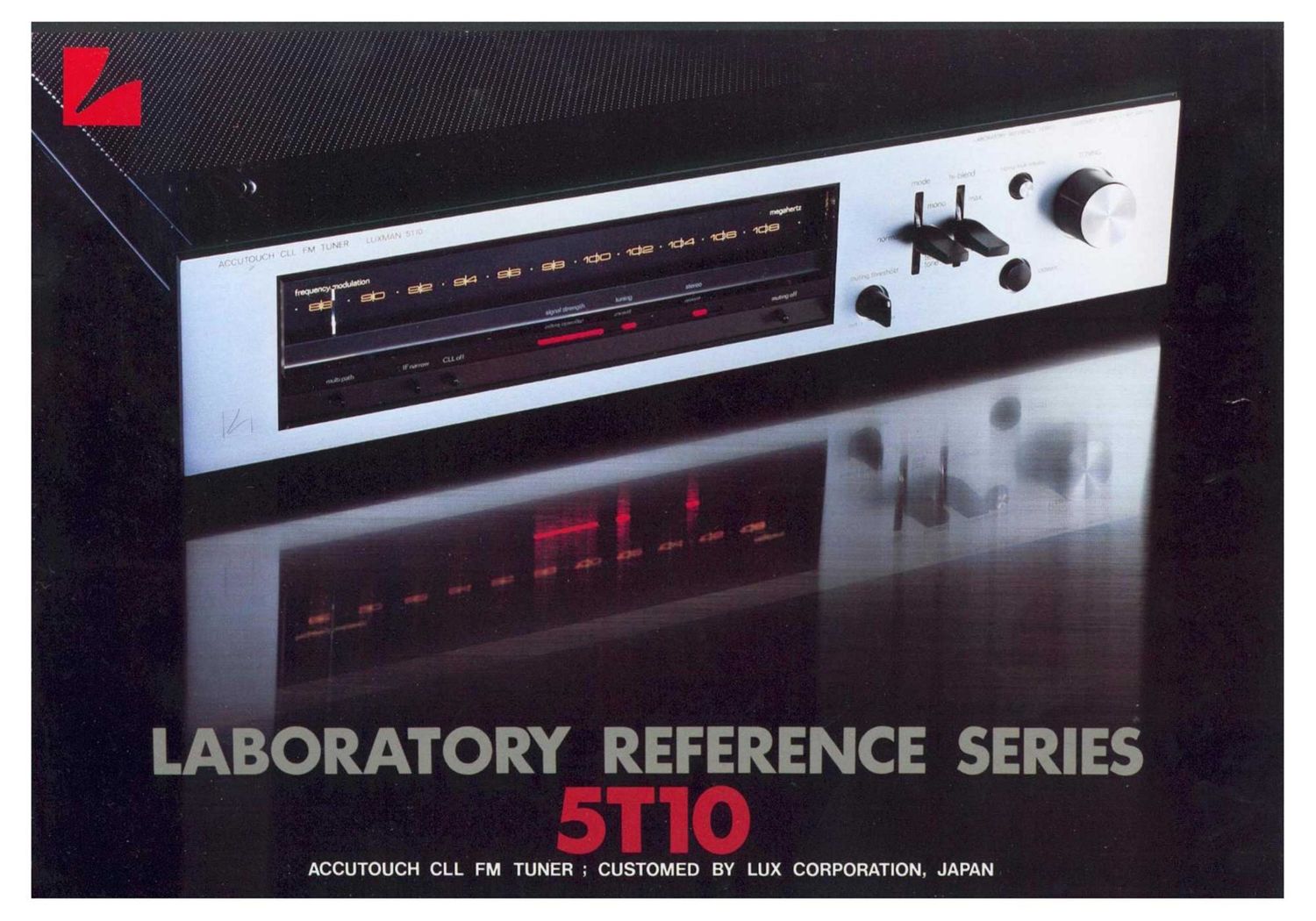
luxman 5 t 10 brochure

Extracted text from luxman 5 t 10 brochure (Ocr-read)


Page 1

LABORATORY REFERENCE SERIES

ACCUTOUCH CLL FM TUNER ; CUSTOMED BY LUX CORPORATION, JAPAN

Page 2

ACCOUTOUCH CLL FM TUNER 5T10

Our original C.L.L. system which has realized quite

accurate and stable tuning condition

We employed our original Closed Loop Locked (C.L.L.) circuit
(pat. pend.) in the STIO to realize extremely accurate and stable
tuning conditions at all receiving FM frequencies. With the C.L.L.
circuitry, total control is effected throughout all the stages, from
the front end to the IF and detector circuits in accordance with
the crystal controlled transmission frequency of a broadcasting
station. Therefore. this may be called the ideal tuning system
offering accurate and stable tuning conditions even if ambient
conditions such as temperature fluctuate. Generally, in the case
of quartz. lock and synthesizer systems, only the local oscillator
or front end is partially controlled by the P.L.L. circuitry. There-
fore it is necessary to design the IF stage and the detector stage
with additional stability.

In addition. C.L.L. circuitry, like the P.L.L. circuit, has the
capture range near the center frequency of the broadcasting

n and the required lock range to achieve a stable receivir

ition. Thus, C.L.L. circuitry always provide the perfe
receiving condition thanks to powerful feedback once the signa.
wave of an FM station is within the capture range and firmly
locked at the lock range. Even if the receiving frequency drifts,
feedback is applied to bring it back to follow the crystal con-
trolled transmission frequency, and stable reception is always
obtained.

In addition, the C.L.L. circuitry incorporates a lockretaining
circuit, and no new locking is needed when power is turned off
and on once the station has been tuned in.

The "ACCUTOUCH" System which makes the most of

the C.L.L. Tuning System

The STIO employs the "ACCUTOUCH" system. This system
makes it possible to tune in all the tuning circuits easily to the
accurate center frequencies of broadcasting stations. To obtain
more precise tuning, an extremely narrow capture range is set
for the C.L.L. circuit of the STIO. It would be hard for a con-
ventional tuning method to obtain sUch a precise tuning point.
since such tuning method requires observation of a center tuning
meter, which is seldom accurate enough.

The ACCUTOUCH system detects the exact center tuning
point utilizing a control voltage at the C.L.L. circuit, which
triggers a mechanical lock on the tuning knob. This is a very
unique system in which the tuning knob is temporarily locked
with a positive response (for about I sec.) at the exact tune-in
point as the knob is gradually turned to locate an FM station.
Precise tuning to a station is possible with an incomparable ac'
curacy compared with that of current visual tuning systems.

IF Bandwidth Selector

In the IF stage, a 2-step bandwidth selector is provided to
provide both excellent distortion and selectivity. In the wide"

Specifications 0 Rtftli'IVlIlt] Frequency 87 SMH: 108MHz o Sufi-"1f?Sf'paffliOH
0 50GB Oumtrng Sensmwty 16 OdBf (3 3uVi
o IHF Usable Sensntuwty l().3dBl ll 8uV) . Mum; Tf"iih*i'ij
o S-gnal tr) Norse Ratio 80dB 0011mm h"""""
0 Frequency Response 20H: - 17,000H; (*0 5GB, mono 81 stereo) .
0 Total Harmowc DistOrt-on (mono) (stem-0) . Um, Voltage
room 0 059;. Iwnde) o 07% (Wide) "~*-""i* "'W'
(HZ 0 0555\- (Widei O 06% (Wild?)
GRHZ O 07% (Wide) 01%(Widei
lkHz O 2% (narrow) 0 5% (narrow)
0 Captum Ratio 0.8dB (Wide), 2dB (narrow)

- Adiacent Channel Seieciivily
O Altvrrmlt Churirwi Selectivity

O Spurious Response Ratio lOOdB
0 IF Respcmse Ratio IDOdB
0 Image Response Ratio lOOdB
0 AM Suppress-on Ratio 62GB

LUX CORPORATION, JAPAN

12d8 (narrow, QOOkHI)

90(18 lnarrow, '400kHzi
30tIB (Wide,

0 Fern Cmisumptlon

O [:JlYlmifflS'QHS

-400kH/)

O Wfrrqhi

l-I. I-chomo. ShimnrrNisMnoehi. Toyonaka-shi. Osaka. 565.JAPAN

position, 2 pairs of wide-bandwidth block filters of good group-
delay characteristics are employed to realize lower distortion,
while in the "narrow" position an additional 2 paris of narrow-
bandwidth ceramic filters are added to offer high selectivity.

DC amp configuration is employed at the Audio Output

Stage. The basic design theme is Sonic Excellence

A 5-gang variable capacitor exclusively designed for FM reccp~
tion is adopted at the front end to make the most of the excellent
characteristics realized after the IF stage. Also superb interference
rejection characteristic is obtained by improving the selectivity
at each RF amplifying circuit.

The IF stage is so designed as to be inherently low in distor-
tion, but to make it perfect, a quadrature wide-bandwidth de
tector circuit is combined with it, which not only realizes low
distortion but high S/N ratio as well.

Of course, a pilot canceller circuit is provided in the multiplex
circuit, but further the phase characteristic of the Iowpass filter
is improved. A DC amp configuration is employed at the audio
output stage. All of these circuit features are specially considered
in terms of good sonic quality.

mo Vocalist-ovum

rune-n a.

45-38 'Vyld", JUHRI 50MB lvv tii'. i'u HR)
45(18 (with? Oer4a'i, 3,0er 'HtN'tlvn, 15H?!
yiiipV 5()0,iV (L'vizdii'ti

lOO (mrrls (fixed),

100 ohms 1 25k ohms (variable!

i\. :tixwrll, 0 iv iv, .shli'i

Tumult: Lmk System, IF BJHUI/Vidih Suleiman
{Mule-r lmlu .itin, Sign. Stu-liq! Ind-natin.
Mullrpnrlx Clwcl- Cm'rrl, Hermann; Test Trum-
Cirrniry FM h,M,-!ir1i_z(;irruit, Mitt rm LiVtE
Adjuster, Trnw delay Mining, Qiiltmt Levi-I
(Tllfli'tfil 75 ohm Ciiaxzai Connector

30W
-i-1?(VJl A Millist ifiiiilln'im
('17 1.3 .32" . 1512-1" r1

Hucltitwtt; was raw; Muir 4w»!
iul ltiki). '18 '1 'ir. 3
Cum». '5'. Mix. ll?) 1' tr:

Printed in Japan

PHONE: 834-2222. TELEX:J63694. CABLELUXELECT OSAKA