Leslie 32h schematics

This is the 1 pages manual for leslie 32h schematics.
Read or download the pdf for free. If you want to contribute, please upload pdfs to audioservicemanuals.wetransfer.com.

Page: 1 / 1
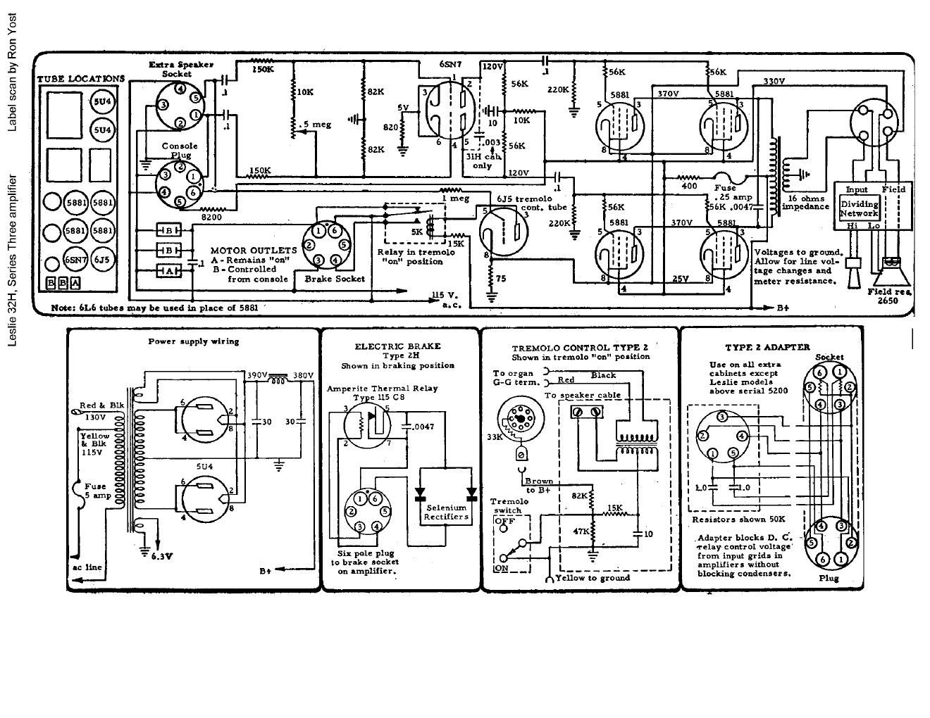
leslie 32h schematics

Extracted text from leslie 32h schematics (Ocr-read)


Page 1

Label scan by Ron Yost

Leslie 32H, Series Three amplifier

r

TUBE LOG AT IONS


in" Spanke-

Socket 150K

__1 A - Remains "on"
B - Controlled

MOTOR OUTLETS

I 5K

L--.----.ll5x

Relay in tremolo
"on" position


II
II
.1
56K
22"" 370V
10K
56K
120V ll__
I ,
.l 400 Fuse
6J5 tremolo - 25 unp 16 ohm:
56K .0047" impedance
310v 5881.


Input

Dividing
Network

Hi

Allow for line vol-

Voltage 5 to ground.

Power Iupply wiring

ELECTRIC BRAKE
Type 21-:
Shown in braking position

390V== 380V
Bfl
Ampetite Thermal Relay
'1' c 115 C8
3/y2\.5
"'30 3° ( 11:430.
3V7
i-
00
Selenium
e a Rectifiers
9 0

Six pole plug
to brake socket
on lmplifier.

l

TRENIOLO CONTROL TYPE 2
Shown in tremolo "on" poniu'on

T o organ
G-G term.

gearszsaél;

W51

cage change: and
ham con-ole Brake Socket meter re'iatance.
, £5 V. Field rel.
L "on: 6].!) tube: ugly be uled in pine: at 5331 -'=- - 5+ 265° 4
Y Y

TYPE 2 ADAPTER

use on all extra
clbinets except
Leslie modela
above serial 5200

to Bl-

Tremolo l
153 | « [5K
I735F 1 |
I ' I --
l l 10

l . . T
l

I

Yellow to ground

Resistor 3 shown 50K

.Adapur blocks D. C.
Telay control voltage
from inpu: grid: in
amplifietl without
blocking condensers.

#{