Kenwood KRFX 9080 D Service Manual
This is the 44 pages manual for Kenwood KRFX 9080 D Service Manual.
Read or download the pdf for free. If you want to contribute, please upload pdfs to audioservicemanuals.wetransfer.com.
Extracted text from Kenwood KRFX 9080 D Service Manual (Ocr-read)
Page 1
J I KRF*X9080D(K) INT 1P( 04.7.28 6:44 AM /\°-»j 1 / \
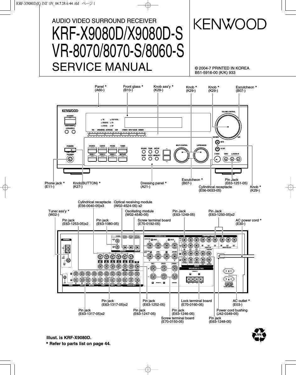
AUDIO VIDEO SURROUND RECEIVER
KRF-X908OD/X908OD-S
VR-8070/8070-S/8060-S
SERVICE MANUAL
BS1 -591 6-00 (K/K) 933
KENWOOD
© 2004-7 PRINTED IN KOREA
Escutcheon *
Panel * Front glass * Knob assy * Knob * Knob *
(A60-) (810-) (K29-) (K29-) (K29-) (307-)
{1 II with] I VOLUME comm
m ammn _
um... m .w .
Asmmsl
nu mm mm as! mmmmm mm
l _______________ I
E -
l. ______________________
POWER mm cmvn man man wmcumm
usm Maui
mu wunm:
01 mi
_@ %%%% 000 VI ~ --©(@-C-©>
Phone jack *
Knob(BU'll'ON) * Dressing panel * (B07-)
/ \ (E11-) (K27-) (A21-)
K /
Cylindrical receptacle Optical receiving module
(E56-0040-05)X3 (W02-4524-05) x2
Tuner assy * Oscillating module Pin Jack
(W02-) (W02-4540-05) (E63-1249-05)
Escutcheon *
Pin . ack
Cylindrical receptacle
(556-0033-05)
Pin Jack
(E63-1250-05)x2
(E63-1251-05)
Knob *
(K29-)
Pin jack Pin jack Screw terminal board AC power cord *
(E63-1253-05)x2 (E63-1080-05) (E70-0192-05) (E30-)
0 e 0
ME "
(
<0 0/
<<7 °>
Pin jack Pin jack Lock terminal board AL outlet *
(E63-1317-05)x2 (E63-1252-05) (E70-O160-05) (1503-)
Pin jack
(E63-1317-05)x2
Pin jack
Pin jack
(E63-1247-05)
(E63-1246-05)
Screw terminal board
(E70-0150»05)
Illust. is KRF-X9080D.
* Refer to parts list on page 44.
Power cord bushing
(J42-0349-05)
Pin jack
(E63-1248-05)
Page 2
KRF7X9080D(K) INT 1P( 04.7.28 6:44 AM N? 2
KRF-X9080D/VR-8070/8060
CONTENTS / ACCESSORIES / CAUTIONS
CONTENTS
CONTENTS / ACCESSORIES / CAUTIONS .............
EXTERNAL VIEW
ADJUSTMENT .....
INTERCONNECTION DIAGRAM
PC BOARD
ACCESSORIES
..2 SCHEMATIC DIAGRAM ............................................
..3 EXPLODED VIEW
..4 PARTS LIST ..........
5
7
SPECIFICATIONS....................................................:59
K
FM indoor antenna (1)
Other countries
(T90-0877-05)
U.S.A. and Canada
(T90-0905-05)
(@7
Remote control unit (1)
(See the below table)
Do
fifioofieawgmm
I yuatoomo
oo omooo. o no
I\ 00 Dougnooo comm
03033299
k
REMOTE CONTROL vs MODEL
AM loop antenna (1)
(T90-0852-05)
Batteries (RB/AA) (2)
MODEL PARTS # REMOTE CONTROL# DESTINATION
$32338 A70-1659-05 RC-R0827 2:;
$333333 A70-1620-05 RC-R0820 i1
$333333 A70-1621-05 RC-R0821 E;
VR-8060-S A70-1622-05 RC-R0822 K3P3
CAUTIONS
Resetting the Microcomputer
while the power is ON, or due to some other external factor.
condition.
the factory.
For the U.S.A. and Canada
The microcomputer may malfunction (unit cannot be operated,
or shows an erroneous display) if the power cord is unplugged
. Please note that resetting the microcomputer will clear the contents
of the memory and return the unit to the state it was in when it left
AC plug adapter (1) -
(E03-0508-00)
I
§ /
Use to adapt the plug on the power
cord to the shape of the wall outlet.
(Accessory only for regions where
use is necessary.)
Unplug the power cord from the wall outlet, then plug
Okey.
it back in while holding down the POWER ONISTANDBY
O Power mode
- Input selector settings
. Picture output
- Speaker ON/OFF
. Volume level
- BASS, TREBLE, INPUT level . Frequency setting
O TONE ON/OFF
I LOUDNESS ON/OFF
- Dimmer level
- MD/TAPE settings
- Listen mode setting
Memory back up function
Please note that the following items will be deleted from the unit's
memory if the power cord is disconnected from the AC outlet for
If approximately 1 day.
this happens, execute the following procedure to reset the
microcomputer and return the unit to its normal operating
O Speaker settings
- Distance setting
O Input mode setting
. Sound mode settings
O Broadcast band
O Preset stations
- Tuning mode
O ACTIVE EQ mode
. SPEAKER EQ mode
For other countries
0) key, press POWER ONIOFF key.
With the power cord plugged in, turn the POWER ONI
OFF key OFF. Then, while holding down the ON/STANDBY