Kenwood KRC 265 S Service Manual

This is the 21 pages manual for Kenwood KRC 265 S Service Manual.
Read or download the pdf for free. If you want to contribute, please upload pdfs to audioservicemanuals.wetransfer.com.

Page: 1 / 21
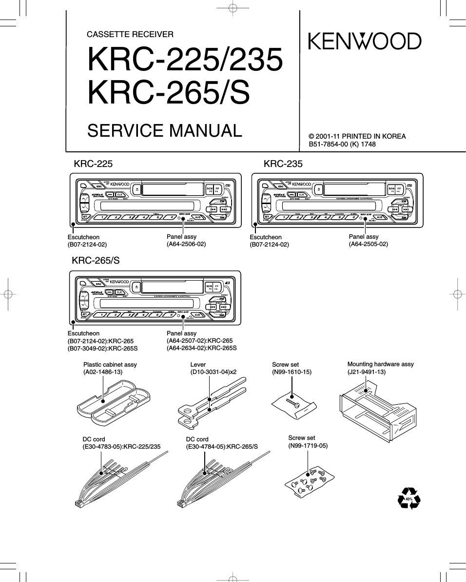
Kenwood KRC 265 S Service Manual

Extracted text from Kenwood KRC 265 S Service Manual (Ocr-read)


Page 6

r\
\J

KRC7225(K)INT,1P 01.10.1811:10AM \°-A:/°6

/\
\/

KRC-225/235/265/2653
MICROCOMPUTER'S TERMINAL DESCRIPTION

OTerminal Description ( |C1 : X14-6850-XX)

Pin No. Pin Name l/O Description Processing Operation
61 ACC DET | ACC detection input Hi : AGO ON
62 B.U. DET | Momentary power down detection input EIUWOEE szgntirépower down detected or
63 S METER | S-meter input from the HE
64 PANEL I Panel detaching detection input Lo : Panel not detached
65 GND | - Connected to GND lines.
66 GND | - Connected to GND lines.
67 HOLD | MI-COM. HOLD input Lo : Hold
68 VDD - VDD connection terminal Connected to B.U. 5V lines.
69 GND | - Connected to GND lines.
70 GND l - Connected to GND lines.
71 ,72 - O - N.C.(Not used)
73 VDD - Positive power supply connection terminal Connected to B.U. 5V lines.
74 GND l - Connected to GND lines.
75 GND l - Connected to GND lines.
76 V88 - Ground connection terminal Connected to GND lines.
77,78 - - N.C.(Not used)
79 GND - TEST terminal 1 Connected to GND lines.
80 XOUT 0 Main clock resonator connection terminal

Page 8

r\
\/

KRC7225(K)INT,1P 01.10.1811:10AM \°-A/8

Set the controls and switches as follows.
BALANCE : center position

+
KRC-225/235/265/2658

ADJUSTMENT

BASS : center position

LOUDNESS : OFF

FADEFt : center position TFtEBLE : center position
OUTPUT RECIEVEFI ALIGNMENT
No. ITEM TAPE ALIGN FOR
SETTINGS SETTINGS POINTS
CASSETTE DECK SECTION

1) During FWD transport adjust ® and 3' so that
line A of 2-LINE TAPE passes through the center
of the head shield plate (core center area)

2) During RVS transport adjust ® and EU so that

HEAD Head Height line B of 2-LINE TAPE passes through the center
I1] HEIGHT 3001659 ' TAPE PLAY Screw of the head shield plate (core center area)

3) Afterthe alignment above, reverse the transport
direction and check the FWD alignment again. If it
is deviated, perform alignment again. (Tape used :
SOC-1659, manufactured by A-BEX)

Connect an AC
2 HEAD TOO-153 voltmeter and TAPE PLAY Head Azimuth Adjust the azimuth for each L ch/Fl ch or FWD/FIVS
I I AZIMUTH 10kHZ oscilloscope to Screw becomes maximum.
SP outputs.
(2-LINE TAPE) TAPE SPEED

B

, HEIGHT @' /®' . . HEIGHT
A (FWD) 6/ (RVS)

(FWD) . 7 .
B \
HEIGHT/AZIMUTH ®/ \® HEIGHT/AZIMUTH
(FWD) (RVS)

A {.