Kenwood KD CMP 925 Service Manual

This is the 42 pages manual for Kenwood KD CMP 925 Service Manual.
Read or download the pdf for free. If you want to contribute, please upload pdfs to audioservicemanuals.wetransfer.com.

Page: 1 / 42
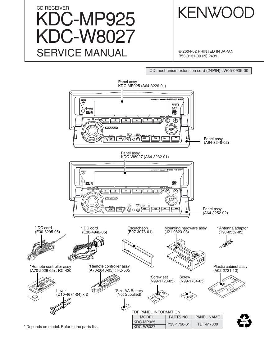
Kenwood KD CMP 925 Service Manual

Extracted text from Kenwood KD CMP 925 Service Manual (Ocr-read)


Page 10

KDC-MP925/W8027

MICROCOMPUTERS TERMINAL DESCRIPTION

10

Pin No. Pin Name l/O Description / Processing Operation
87 FL LATCH O Latch output to FL driver IC

88,89 NC - NC

90 REMO ON 0 Power supply control for remote control IC (H :ON, Hi-Z :OFF)

91 FL3.3V SW 0 FL3.3V control terminal (H :ON, Hi-Z :OFF)

92 FL+B SW 0 FL+B control terminal (H :ON, Hi-Z :OFF)

93 3.3V SW 0 3.3V control terminal (L :ON, Hi-Z :OFF)

94 NC - NC

95 OE O OE control for Flash ROM (L : DATA transmission, Hi-Z :Wait ready)
96 NC - NC

97 WE/WR O WRITE/READ control for Flash ROM (L :Writing, Hi-Z :Wait ready)
98 3.3V VDD AVR 3.3V

99 EVSS - GND

100 CE ROM 0 CE control tor ROM (L : DATA transmission, Hi-Z :Wait ready)

101 CE F/ROM 0 CE control tor Flash ROM (L :DATA transmission, Hi-Z :Wait ready)
102 FLASHROM CHECK 0 Writing condition check for Flash ROM (H :OK, L :NG)

103,104 NC - NC

105 GREEN LED 0 Select lor illumination (GREEN H :ON, L :OFF)

106 RED LED 0 Select tor illumination (RED H :ON, L : OFF)

107 DISP LED 0 DISP LED control (Normal H: ON, L : OFF)

108 BLACK DISP 0 Light up to DISP LED (H :ON, L : OFF)

109,1 10 NC - NC

111 SA RST 0 Reset for spectrum analyzer (H : Reset, L : Normal)

112 3.3V VDD - AVR 3.3V

1 13 EVSS - GND

1 14~1 17 NC - NC

118~123 A21 ~A16 0 Address bus

124 2.5V VDD - AVR 2.5V

125 VSS - GND

126~133 A15~A8 0 Address bus

134 3.3V VDD - AVR 3.3V

135 EVSS - GND

136~143 A7~A0 0 Address bus

144 D15 l/O External ROM data input/output terminal