Kenwood DPFR 4010 E Service Manual

This is the 17 pages manual for Kenwood DPFR 4010 E Service Manual.
Read or download the pdf for free. If you want to contribute, please upload pdfs to audioservicemanuals.wetransfer.com.

Page: 1 / 17
Kenwood DPFR 4010 E Service Manual

Extracted text from Kenwood DPFR 4010 E Service Manual (Ocr-read)


Page 1

CDiZO3/DEFiR30llNK) COVER( 98.4.2411:3OPM y [W 2

Eufitgllé/(Dfiiilgfigm0/DPF-R3010E KENWOOD
CD-204/DPF-R4010/DPF-R4010E
SERVICE MANUAL

© 1998-3/851-5417-00 (K/K) 3430

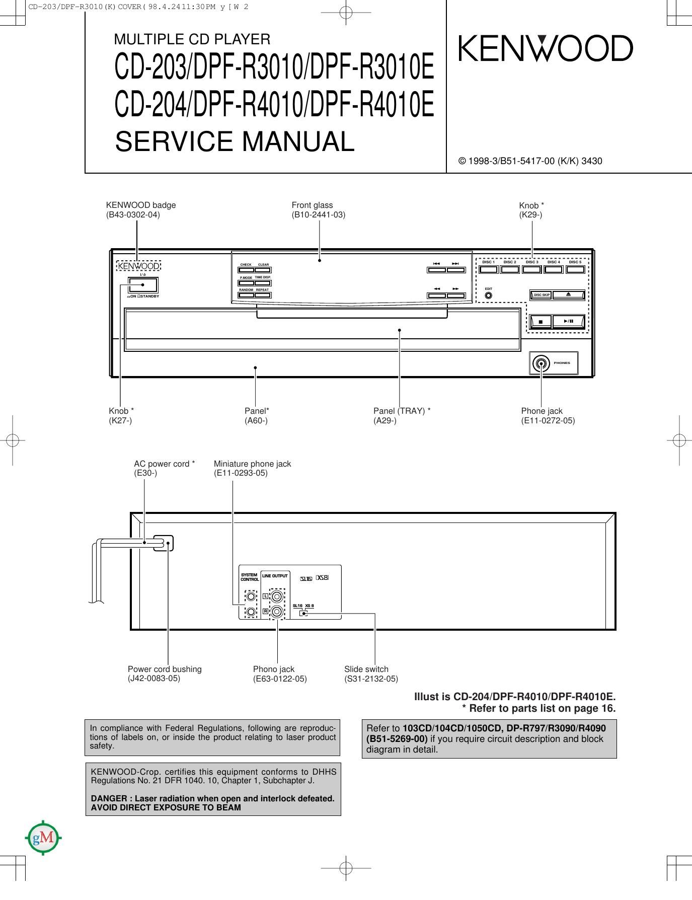
KENWOOD badge Front glass

Knob
(343-0302-04) (810-2441-03) (K29-)
w _D_: .

E

non LisuNnav

Knob Panel Panel (TRAY) Phone jack
(K27-) (A60-) (A29-) (E11-0272-05)

AC power cord * Miniature phone jack
(530-) (E11-0293-05)

I?

Q

SVSVEM uua amvur

Power cord bushing Phono jack Slide switch
(J42-0083-05) (E63-0122-05) (331-2132-05)
Illust is CD-204/DPF-R4010/DPF-R4010E.
* Refer to parts list on page 16.
In compliance with Federal Regulations, following are reproduc- Refer to 1OSCD/104CD/1OSOCD, DP-R797/R3090/R4090
tions of labels on, or inside the product relating to laser product (351-5259.oo) if you require circuit description and block
saew- diagram in detail.

KENWOOD-Crop. certifies this equipment conforms to DHHS
Regulations No. 21 DFR 1040. 10, Chapter 1, Subchapter J.

DANGER : Laser radiation when open and interlock defeated.
AVOID DIRECT EXPOSURE TO BEAM

Page 3

CDiZO3/DPFiR30lINK) COVER( 98.4.2411:3OPM y [W 6 /\
K7

1. Pin description

CD-203/204/DPF-R3010/RSOIOE/R4010/R4010E

CIRCUIT DESCRIPTION

Pin No. Name I/O Function
1~7 7G~1 G 0 Display digit control (Grid7~Grid1)
8 VDD Power supply (+5V)
9 SQCK O Q data reading clock output
10 NC 0 Unused
11 SUBQ | Q data input
12~15 KR3~KRO I Key return 3~0
16 NC | Unused
17 W | Reset input L: RESET
18 SLT SW | CDM25 start limit switch input L : SW ON
19 W l CDM25 mechanism down switch input L : SW ON
20 AVSS l Unused (connected to VSS)
21 W l CDM25 mechanism up switch input L : SW ON
22 m l CDM25 close switch input L : SW ON
23 WW I CDM25 open switch input L : SW ON
24 OPEN M 0 Open motor control H :ACTIVE
25 CLOSE M 0 Close motor control H : ACTIVE
26 RTRAY R 0 Rotary tray motor control (CW) H : ACTIVE
27 RTRAY L 0 Rotary tray motor control (CCW) H : ACTIVE
28 RTRAY S 0 Rotary tray motor control (deceleration) H : ACTIVE
29 AVDD Unused (connected to VDD)
30 AVREF Unused (connected to VSS)
31 NC | Unused
32 XT2 Unused (OPEN)
33 V88 GN D
34 X1 I System clock input
35 X2 Unused
36 DSENSE | CDM25 disc sensor detection
37 PSENSE | CDM25 position sensor detection
38 W 0 Laser signal output L : LASER ON
39 FOK | FOK signal input H : FOCUS ON
40 D.R.I.V.E | Unused
41 SERIAL SW | Serial communication 8 (XS8)/16(SL16) bit changover H : 16 BIT
42 SDATA I/O System serial data signal input output
43 BUSY I/O System serial busy signal input output
44 SCOR | Sub code frame sync detection
45 MON 0 Focus drug countermeasure circuit control
46 MUTG 0 Digital mute control H : MUTE ON
47 REM I Remote control signal input
48 VPP GND
49 SENSE | Sense input from CXD2507AQ
50 DTA 0 Data output for CXD2507AQ
51 CLK O Clock output for CXD2507AQ
52 VDD Power supply (+5V)
53,54 DEFECT SEL/NC l Unused
55 LAT O Latch output for CXD2507AQ
56 GFS l Frame signal input
57 RMUTE 0 Analog mute control L : MUTE ON
58 MDT 0 Attenuater data output
59 MCK O Attenuater clock output
60 MEL 0 Attenuater latch output
61 ~70 Sp~Sg/KS 0 Display segment control (Seg p-Seg g) / Key scan
71 VLOAD Display drive negative power supply (-35V)
72~77 St~Sa/KS 0 Display segment control (Seg f-Seg a) / Key scan
78~80 IOG-BG 0 Display digit control (Grid10-Grid8)

\
i;