Kenwood DNX 5380 Service Manual
This is the 122 pages manual for Kenwood DNX 5380 Service Manual.
Read or download the pdf for free. If you want to contribute, please upload pdfs to audioservicemanuals.wetransfer.com.
Extracted text from Kenwood DNX 5380 Service Manual (Ocr-read)
Page 1
MONITOR WITH DVD RECEIVER NAVIGATION SYSTEM
DNX42808T/5180/52808T
/5380/5380M/53808T
/558OBT/6040EX/6180
KENWOOD
Kenwood Corporation
/64BOBT/6980
SERVICE MANUAL
© 2011-3 PRINTED IN JAPAN
B53-0849-00 (N) 303
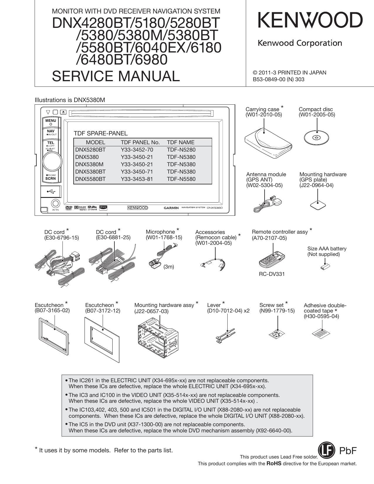
Illustrations is DNX5380M
7 7 7 7 7 Carrying case" Compact disc
V D E' Le 7 7 7 7 7 7 7ij (w01-2010-05) (wo1-2005-05)
MENU \ / l
d) 7
3153's TDF SPARE-PANEL ©
2 MODEL TDF PANEL No. TDF NAME
DNX52803T Y33-3452-70 TDF-N5280
] \ DNX5380 Y33-3450-21 TDF-N5380
I DNX5380M Y33-3450-21 TDF-N5380
DNX5SSOBT 333450-71 TDF-N5380 Antenna module Mounting hardware
DNX55803T Y33-3453-81 TDF-N5580 (GPS ANT) (GPS plate)
(W02-5304-05) (J22-0964-04)
/ \ ?$
3 W .22 "annals; 13:. mm mm: O
I I
DC cord * DC cord * Microphone * Accessories Remote controller assy *
(E30-6796-1 5) (E30-6881-25)
(WO1-1768-15)
Escutcheon *
(807-3172-12)
Escutcheon *
(807-3165-02) (J22-0657-03)
Mounting hardware assy *
(Remocon cable)
(A70-2107-05)
(WO1-2004-05)
Size AAA battery
(Not supplied)
2% 1
@
RC-DV331
Lever * Screw set * Adhesive double-
(D10-7012-04) x2 (N99-1779-15) coated tape *
I (H30-0595-04)
®
.
OThe |C261 in the ELECTRIC UNIT (X34-695x-xx) are not replaceable components.
When these |Cs are defective, replace the whole ELECTRIC UNIT (X34-695x-xx).
'The |C3 and |C1 00 in the VIDEO UNIT (X35-514x-xx) are not replaceable components
When these le are defective, replace the whole VIDEO UNIT (X35-514x-xx) .
'The |C103,402, 403, 500 and ICSO1 in the DIGITAL |/O UNIT (X88-2080-xx) are not replaceable
components. When these |Cs are defective, replace the whole DIGITAL I/O UNIT (X88-2080-xx).
'The |C5 in the DVD unit (X37-1300-00) are not replaceable components.
When these |Cs are defective, replace the whole DVD mechanism assembly (X92-6640-00).
* It uses it by some models. Refer to the parts list.
This product uses Lead Free semen.
This product complies with the ROHS directive for the European market.
Page 6
DNX4280BT/5180/5280BT/5380/5380M
/5380BT/5580BT/6040EX/6180/6480BT/6980
COMPONENTS DESCRIPTION
0 ELECTRIC UNIT (X34-695x-xx)
Ref. No. Application / Function Operation / Condition / Compatibility
|C1 Power IC Power AMP
|02 Multi channel Voltage Regulator ILMSV, CD8V, A8l5V, SW5V, BUSV Power Supply
IC4 S-terminal Regulator TMCS.3V Power Supply
IC71 Voltage Converter +9V, ~9V Power Supply
|0231 RDS Decoder IC RDS Signal Processing etc
|0261 FM & RDS Receiver Tuner for TMC
IC301 Electoric Vol lC Audio Vol Control, Audio Signal Select
IC371,381,391 OP amp 5V Pre out AMP
IC401 Audio selector 10 Audio Signal Select
|0571 AND (4) logic lC KAB signal level shift
071,72 +9V, ~9V Power Supply control
073 +9V, -9V Power Supply
07475 +9V, ~9V Power Supply control
076 -9V Power Supply
077,78 +9V, ~9V Power Supply control
079 +9V Power Supply
080 +9\/, ~9V Power Supply control
0111 Reverse Detect
0121 Parking Detect
0131 Illumi Detect
0151 ACC Detect
0201 AM+B Power Supply
0202 AM+B Power Supply control
0241 ANT Distributer
0341 Preout FL mute
0342 Preout FR mute
0343,344 Preout mute drive
0351 Preout RL mute
0352 Preout RR mute
0361 Preout SWL mute
0362 Preout SWR mute
0363,364 Preout mute drive
0573,574 KABiTX short protection
0575 KAB+B Power Supply control
0576 KAB+B Power Supply
0 VIDEO UNIT (X35-514x-xx)
Ref. No. Application / Function Operation / Condition / Compatibility
|C1 Logic Waveform shaping
ICZ Logic AND
IC3 DCDC controller LCD Backlight power supply
IC4 Logic AND
Page 18
DNX4280BT/5180/5280BT/5380/5380M
/5380BT/5580BT/6040EX/6180/6480BT/6980
18
TEST MODE
2.2.1.3 CMOS-300 communication line test
Start the communication with CMOS-300 by pressing [Rear
Camera] key.
When the communication is successful, OK" is displayed,
and if it has failed, NO is displayed (refer to the Figure
2.2.1.3).
This test is disabled for the models with X" listed in the
Ext SW column of Table 1.2.1.
Rear Camera
Rear Camera
Figure 2.2.1.3 CMOS-300 communication line test result screen
Key Specification
Return : Transfer to Test Mode Main screen.
2.2.1.4 Direct Select
It will transfer to Top Menu screen of product mode while
continuing in the test mode when [Direct Select] key is
pressed.
The following operation is transferred to Test Mode Main
screen while displaying the GUI screen of the product
mode.
I Press the [MENU] key in the panel ([MENU] key at the bot-
tom left of the screen will operate as normal even during
the test mode)
I Press Tenkey4 on the remote controller
2.2.1.5 DRAM Check
Display the DRAM Check result at the top right of the Test
Mode Main screen. (For details about the DRAM Check re-
sult, refer to the Table 2.2.1.4)
DRAM Check Displayed character Background color of
result string the character string
OK DRAM OK No specification
NG DRAM NG Red
Table 2.2.1.4 DRAM Check result display
Check method
@Transfer to the test mode. (At this time, DRAM N6"
is displayed at the top right of the screen, but ignore it
here)
(2) Perform ACC OFF/ON.
(39 Test Mode Main screen is displayed. Display at this time
is the result of DRAM check.
2.2.1.6 LCD Backlight automatic adjustment value display
Display the current LCD Backlight automatic adjustment
value close to the [LCD Backlight] key.
Make the display region red when the automatic adjustment
value is not between 2 and 8.
2.2.2 Information screen
This screen is to display such information as version num-
ber and other conditions.
The contents displayed on the Information screen are
shown in Figure 2.2.2.
Information
DNX _-
Application Processor
[System prcom | Venn/v [ [Panelurcom [ Vaxtx [
Capacitance Detection lC
l Mister | Vw l l ET Module l v~.«.~ l
l ovsa7xx F/E | vW [ l PlN Code [ [
l DVSa7>
[Serial | W[ l DC Offset l None l
Figure 2.2.2 Information screen
Key Specification
Return : Transfer to Test Mode Main screen.
Hide Capacitance Detection IC for the models with X
listed in the Electrostatic touch column of Table 1.2.1.
Hide BT Module" and PIN Code" for the models with X"
listed in the BT built-in column of Table 1.2.1.
Hide DivX Codec Version" for the models with X" listed in
the DivX column of Table 1.2.1.
2.2.3 Service screen
This screen is to show a variety of service information.
The contents displayed on the Service screen are shown in
Figure 2.2.3.
Servtce
Inlt PowerON in») minutes
Serial
Imt DVDrVideo mminutes IDES
Init MonitorOpen umime:
In
IStan
oivx Registration Code Clear
Tuner Mule Level
DVSB7OD Adjust
II
I Ill
Return
Figure 2.2.3 Service screen
Page 24
DNX428OBT/5180/528OBT/5380/5380M
/53808T/5580BT/6040EX/6180/6480BT/6980
24
TEST MODE
I Af'ter pressing the [Signal] key, acquire 100 samples of the
data for each Key, and calculate its average (SignaLave).
Wait is displayed in the status display area during the
test.
I Display OK" in the Signal result display area for each Key
if the SignaLave/ Noise27.
I Display NG in the Signal result display area for each
Key if the SignaLave/ Noise<7.
Display End in the status display area once all the re-
sults for each Key are displayed.
I Make it so that re-test of the Key that was NG as a result
of the Signal test is possible
The following is the procedure for the re-test.
Q) Touch the electrostatic touch key to re»test. (Simulta-
neous re-test is possible when there are multiple elec-
trostatic touch keys to re-test.)
CZ) Press [Signal] key. This will start the re-test of the Key
that was NG with the previous Signal test (sampling
numbers, calculation method of values criteria for
determining OK/NG for the re-test will be same as nor-
mal.)
Wait is displayed in the status display area, ass in
the Signal result display area, and ease" in SignaLave
value display area during the re-test.
(3) End" is displayed in the status display area and test
result is displayed in the Signal result display area once
the re»test is completed.
I It will transfer to Test Mode Main screen and the panel
is moved to the default position when the [Return] key is
pressed.
2.2.11 Development screen
This is a screen to display the table for multiple key press-
ing specification. Also, make this screen possible to start
from bmp,View.exe.
Figure 2.2.11-A shows the display with the Development
screen (list contents of Table 2.3.2).
Development
Operallon
Test Mode ON
Span Changing
Clear DC OllseI/Service/Memmy/Dther
Demo Mode ON
oeme Mode or;
Ros Field Test Mode ON
Opening screen Custemtze
aiueteetn centrtcetten Mode ON
Key (Mid)
MENU + Arr s Reset
Eject s NAV + Reset
MENU + AUD+ Reset
Elect + AUD + Reset
MENU + Reset
Elem + Volume Down + Reset
MENU + Volume Down + Reset
NAV + AUD + Reset
KEY (Envy)
Elem + SCRN + Reset
Elem + AW + Reset
MENU + AW + Reset
MENU + scRN + Reset
MENU + Reset
Eject s TEL + Reset
MENU + TEL + Reset
Elect + NAV + Reset
bmpjtew exe | l Steering Remote | l Return
Figure 2.2.11-A Development screen
Key Specification
bmp,View.exe
: Startup bmp,View.exe.
Connect the USB memory containing bmp,View.exe.
Steering Remote
: Transfer to steering remote controller screen.
Display this key as inactive for the models with X "
listed in the Steering Remote column of Table 1.2.1.
Return : Transfer to Test Mode Main screen.
USB memory folder/ file structure
Figure 2.2.11-B shows the folder/ file structure of the USB
memory containing bmp,View.exe.
USB Memory D Bmp View.e>
E7720 77D aaaaa1.bmp
fa aaaaaM.bmp
E7800 -D bbbbb1.bmp
7D bbbbbivbmp
Figure 2.2.11»B USB memory folder/ file structure
2.2.12 Steering Remote test screen
Perform the test for Steering Remote.
Figure 2.2.12 shows the display contents of the Steering
This test is not performed for the models with X" listed in
Steenng Remote Test
Steenng Remete Test
|:> All items OK
Steering Remote Test
,
More than t NG
Figure 2.2.12 Steering Remote test screen
Key Specification
Remote test screen.
the Steering Remote column of Table 1.2.1.
Return : Transfer to Test Mode Main screen.
Page 27
DNX4280BT/5180/5280BT/5380/5380M
/538OBT/5580BT/6040EX/6180/6480BT/6980
TEST MODE
PS automatic determination when selecting station
CD Select a station and receive the PS.
Q) Turn off the PiANT and P,CON terminals if the received
PS is RDSJEST or KENWOOD, L: Space).
2.2.13.5 Unit ID screen
Copy the Unit ID, Unlock Code, and GMA in the uSD to the
NAND memory.
Prohibit transfer to the Unit ID screen in the release version
(Vx.x.0).
This screen is a screen for designing purposes, so copy
the Unit ID, Unlock Code, and GMA unconditionally to the
NAND memory.
Figure 2.2.13.5 shows the display contents of the Unit ID
screen.
Unit ID Unit D
Write DK/NG
:>
Cancel
Figure 2.2.13.5 Unit ID screen
Key Specification
Copy : Start copying Unit ID, Unlock Code, and GMA.
Cancel : Transfer to Navigation Test screen.
Return : Transfer to Navigation Test screen.
2.3 Functional specification
This section describes the test mode specification in each
function.
2.3.1 Display
During the test mode, other than the screen described in
2.2, it is possible to transfer to the screen displayed nor-
mally, such as Source Control screen, Audio Control screen,
Setup screen, etc.
(Press [Direct Select] key in the Test Mode Main screen to
transfer)
Do not perform Touch cursor display on the 11 Visual Mid/
Entry model.
2.3.2 Key
Even in the Test mode, the specifications of the hard key
shall be the same as while in normal operation. (Except for
[MENU] key)
For your reference, the multiple pressing specifications of
the key are described in Table 2.3.2.
(For original documents of multiple key pressing specifica»
tion, refer to the 11 Function specificationihard key")
Operation
Multiple press key
Mid
Entry
Test Mode ON
MENU + A'Il' + Reset
Eject + SCRN + Reset
Span switching
Eject + NAV + Reset
Eject + ATI' + Reset
DC Offset/ Service/
Memory Other Clear
MENU + AUD + Reset
MENU + AIT + Reset
Retailer mode: ON
Eject + AUD + Reset
MENU + SCRN + Reset
Retailer mode: OFF
MENU + Reset
MENU + Reset
RDS test drive Eject + Volume Down _
Eject + TEL + Reset
mode ON + Reset
Opening screen MENU + Volume Down MENU + TEL + Reset
customization + Reset
Bluetooth authenti-
cation mode ON
NAV + AUD + Reset
Eject + NAV + Reset
Table 2.3.2
(for reference) Multiple pressing key specifications
* Due to the restriction of the electrostatic touch sensor IC
(PSoC), perform multiple press + Reset operation as de-
scribed below for the Mid model.
(D Perform the key operation while the set is Powered
ON. (When Backup ON is performed while pressing
the key or key is operated in the Power OFF status,
key data cannot be acquired.)
(2) In case of [MENU] key + other key ([A'IT], [AUD], [Vol-
ume Downj), press the other key first, then the [MENU]
key, and then the [Reset] key, or press [MENU] key
+ other key while holding down the [Reset] key, and
then release the [Reset] key. (Because it will transfer
to Power OFF after the [MENU] key is pressed for 1
second)
2.3.3 Remote controller
The remote controller key specification is listed in Table 2.3.3.
(Note that the keys that are not listed in the table have con»
ventional functions.)
Remote controller key specification shown in Table 2.3.3 is
when the SW at the side of remote controller is set to AU»
DlO.
Key Operation
FM DVD video inspection mode
AM DVD audio inspection mode
Tenkey #0 Transfer to the Flicker Adjustment screen
Tenkey #2 Set the Volume value as Step26
Tenkey #4 Transfer to Test Mode Main screen
Tenkey #5 Forcible Navigation Voice Interruption ON/OFF
Transfer to the Screen Adjustment screen (Screen
Tenkey #6 adjustment screen is cancelled when the Screen
adjustment screen is displayed)
27
Page 90
DNX428OBT/5180/5280BT/5380/5380M
/53808T/5580BT/6040EX/6180/6480BT/6980
>I< New parts
Parts without Parts No. are not supplied.
Les articles non mentionnes dans la Parts No. ne sont pas fournis.
Teile ohne Parts No. werden nicht geliefert.
PARTS LIST
A N
Ref. No. 3 iv Parts No. Description 3:3): Ref. No a 32: Parts No. Description REIT;
DNX42BOBT/5180/5280BT/5380/5380M/5380BT/5580BT 234 1C * 601-4778-04 TORSION COIL SPRING M(MQC(
DNX6°4°EXI 6180548031" 693° 235 10 >1: (301»4779-04 TORSION COIL SPRING mm
203 1C >I< A22-3301-21 SUB PANEL ASSY EIQ1X1 235 10 >I< G01-4779-04 TORSION COIL SPRING M1M201
203 10 >I< A22-3301-21 SUB PANEL ASSY MIMZC1 239 3D G16-1750-14 SHEET
205 1D >I< A52-1160-02 TOP PLATE
RC1 1E A70-2107-05 REMOTE CONTROLLER AS (RC»DV331) KR101 >I< H54-4960-03 ITEM CARTON CASE K
RC1 1E A70»2107-05 REMOTE CONTROLLER AS (RC»DV331) X1M1M2 >I< H54-4961»03 ITEM CARTON CASE K1
>I< H54-4962-03 ITEM CARTON CASE K2
RC1 1E A70-2107-05 REMOTE CONTROLLER AS (RC»DV331) C1 >I< H54-4963»03 ITEM CARTON CASE R1
>I< H54-4964-03 ITEM CARTON CASE E1
>I< 859-2045-00 SUB-INSTRUCTION MANUAL (ENGSPA KK1 K2
>I< 859-204500 SUB-INSTRUCTION MANUAL (ENGSPA R1 K3 >I< H54v4965-03 ITEM CARTON CASE E2
» >I< 8592046-00 SUB-INSTRUCTION MANUAL (FRE) KK1K2 >I< H54-4966»03 ITEM CARTON CASE Q1
>I< 859-2046-00 SUB-INSTRUCTION MANUAL (FRE) K3 >I< H54-4967-03 ITEM CARTON CASE X1
>I< 859204700 SUB~INSTRUCTION MANUAL (POR) R1 >I< H54-4968»03 ITEM CARTON CASE K3
>I< H54v4969-03 ITEM CARTON CASE M1
» >I< 8592048-00 SUB»INSTRUCTION MANUAL (ENG) EIE201
>I< 859-2049-00 SUBINSTRUCTION MA (FREGERDUT E1E2 >I< H54-4970»03 ITEM CARTON CASE M2
>I< 859-2050-00 SUB»INSTRUCTION MANUAL (RUS) Q1 - >I< H54-5034-03 ITEM CARTON CASE C1
>I< 859-2051»00 SUB-INSTRUCTION MANUAL (ENG) X1M1M2 241 1E H30-0595-04 ADHESIVE DOUBLE-COATED TAPE X1M1M2
>I< 8502051-00 SUBINSTRUCTION MANUAL (ENG) C1 241 1E H30-0595-04 ADHESIVE DOUBLE-COATED TAPE C1
>I< 859-2052-00 SUB-INSTRUCTION MANUAL (SCHI) MICI 244 1E J22-0657-03 MOUNTING HARDWARE ASSY KK1K2
>I< 859-2053-00 SUB~INSTRUCTION MANUAL (ARA) M2 244 1E J22-0657-03 MOUNTING HARDWARE ASSY R1E1E2
>I< 859-2068-00 SUB-INSTRUCTION MA (ITASPAPOR E1 E2 244 1E J22-0657-03 MOUNTING HARDWARE ASSY Q1 K3
» >I< B64-4795-00 INSTRUCTION MANUAL (ARA) M2 245 1F J22-0964-04 MOUNTING HARDWARE (GPS PLATE)
>I< B64-4796-00 INSTRUCTION MANUAL (S-CHI) C1
252 3C L92-0638-05 FERRITE CORE
>I< B64-4857»00 INSTRUCTION MANUAL (ARA) M2
- >I< B64-4859-00 INSTRUCTION MANUAL (S-CHI) C1 253 1E N35-2008-43 BINDING HEAD MACHINE SCREW EIO1X1
206 1E 807-3165-02 ESCUTCHEON KK1 K2 253 1E N35-2008»43 BINDING HEAD MACHINE SCREW M1M201
206 1E BO7»3165-02 ESCUTCHEON R1E1E2 254 1E N99-1779-15 SCREW SET KK1 K2
206 1E BO7-3165-02 ESCUTCHEON 01X1K3 254 1E N99-1779-15 SCREW SET R1X1 K3
254 1E N99-1779v15 SCREW SET M1M2C1
206 1E 807-3165-02 ESCUTCHEON M1 M2
207 1F BO7-3172-12 ESCUTCHEON X1M1M2 A 30 N09-6425»15 MACHINE SCREW (M3.0X5)
207 1F BO7~3172~12 ESCUTCHEON C1 B 20 N09-6821»05 MACHINE SCREW
C 2D >I< N09-6848-15 TAPTITE SCREW
210 1E D10-7012-04 LB/ER KK1 K2 D 1D >I< N09-6851»05 MACHINE SCREW
210 1E D10-7012-04 LB/ER RIE1E2 F 20 N35-2614-48 BINDING HEAD MACHINE SCREW
210 1E D10-7012-04 LB/ER Q1 K3
G 10 N82-2007»47 BINDING HEAD TAPTITE SCREW E101X1
DC1 1E E30-68B1»25 DC CORD KK1 K2 G 10 N82-2007-47 BINDING HEAD TAPTITE SCREW M1M2C1
DCI 1E E30-6881-25 DC CORD R1X1 K3 H 20 N82-2608»43 BINDING HEAD TAPTITE SCREW
DCI 1E E30-6881-25 DC CORD MIM2C1 J N86-2606<48 BINDING HEAD TAPTITE SCREW
DC2 1E E30-6796-15 DC CORD (ISO) E1 E201 K 20 N86-2608»43 BINDING HEAD TAPTITE SCREW E101X1
FC1 1D >I< 539419305 FLAT CABLE
K 20 N86-2608»43 BINDING HEAD TAPTITE SCREW M1M201
FC2 2D >I< E39-1194-05 FLAT CABLE
FC3 2D >I< ESQ-119705 FLAT CABLE KR1 255 1F W01-1768-15 MICROPHONE KK1 K2
FC4 3D >I< ESQ-119305 FLAT CABLE 255 1F W01-1768-15 MICROPHONE RIE1E2
WH1 3D >I< ESQ-121605 WIRING HARNESS X1M1M2 255 1F W01-1768-15 MICROPHONE Q1X1
WH1 3D >I< E39-1218-05 WIRING HARNESS C1 256 1E >I< W01-2004-05 ACCESSORIES (REMOCON CABLE) X1M1M2
256 1E >I< W01-2004»05 ACCESSORIES (REMOCON CABLE) C1
217 2C >I< F07-223902 COVER EIQ1X1
217 2C >I< F07-2239-02 COVER MIM2C1 257 1F >I< W012005-05 COMPACT DISC (MANUAL)
218 1D F09»2929-04 CAP (USB) KK1 K2 258 1F >I< W01-2010-05 CARRYING CASE E1Q1X1
21 8 1D FOB-292904 CAP (USB) R1E1E2 258 1F >I< W01-2010»05 CARRYING CASE M1M2C1
21 8 1D FOB-292904 CAP (USB) Q1 K3 259 1E W02-5304-05 ANTENNA MODULE (GPS ANT)
260 1D >I< W02-5475-35 NAVIGATION MODULE K1K2K3
219 2C >I< F09»3070»05 FAN
228 3C >I< F19»1839-03 COVER (DUCT) 260 1D >I< W02-5476-35 NAVIGATION MODULE E2
F1 20 F52»0024-05 FUSE (MINI BLADE TYPE) 15A 260 1D >I< W02-5477-35 NAVIGATION MODULE K
260 1D >I< W02-5478-35 NAVIGATION MODULE E1
234 10 >I< G014778-04 TORSION COIL SPRING EIQ1X1 260 1D >I< W02-5479-35 NAVIGATION MODULE RIOIXI
K: DNX6980 K1: DNX6180 K2: DNX604OEX K3: DNX51BD (North America) Alndicates safety critical components.
E1: DNX52BOBT E2: DNX4280BT (Europe) 01: DNX558OBT (Russian)
90 R1: DNX6480BT (Latin America) X1: DNX5380BT (Australia)
01: DNXSSBO (China)
M1: DNX5380 M2: DNX5380M (Other Areas)