Kenwood DMSE 7 G Service Manual

This is the 22 pages manual for Kenwood DMSE 7 G Service Manual.
Read or download the pdf for free. If you want to contribute, please upload pdfs to audioservicemanuals.wetransfer.com.

Page: 1 / 22
Kenwood DMSE 7 G Service Manual

Extracted text from Kenwood DMSE 7 G Service Manual (Ocr-read)


Page 1

DMeSE92,CO\/ER(98.4.2422132 y[W 2 /\
K

BNiD/ilcsREEcciiéRB G /SE9 KENWOOD

SERVICE MANUA

© 1997-11/851-5395-00 (K/K) 3191

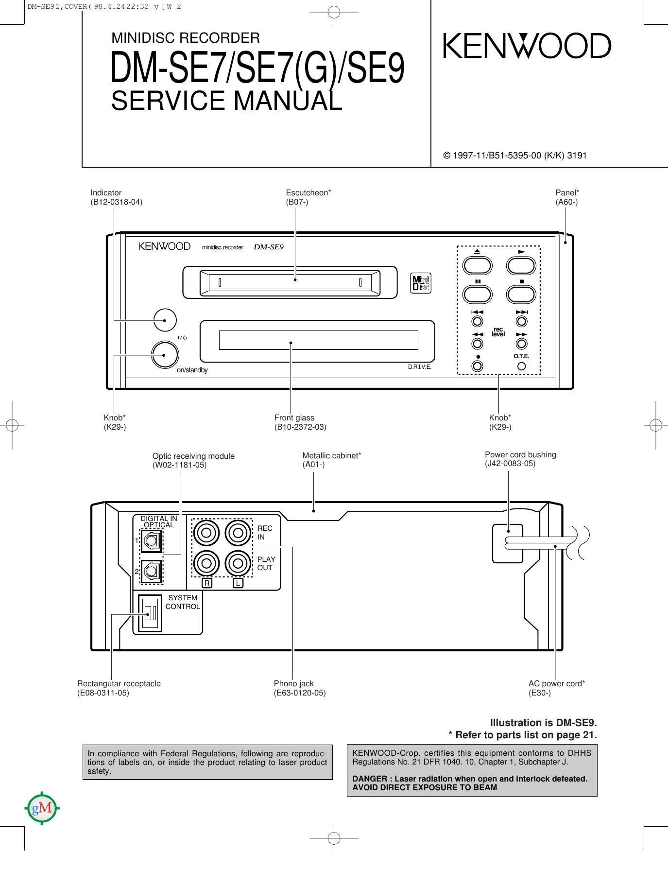
Indicator Escutcheon Panel
(B12-0318-04) (807-) (A60-)

KENWOOD minidiscreoomier DMVSEQ """"""""""'.

[/1 I]
Q

l/(J

art/standby

10

Knob From glass Knob A

'\
c (K29-) (Bl 0-2372-03) (K29-) @
Optic receiving module Metallic cabinet Power cord bushing
(W02-1181-05) (AO1-) (J42-0083-05)


DIGITAL IN
gAL

SVSTEM
CONTROL

Rectangutar receptacle Phone Jack AC power cord
(E08-0311-05) (E63-0120-05) (E30-)

Illustration is DM-SEQ.
* Refer to parts list on page 21.

In compliance with Federal Regulations, following are reproduc- KENWOOD-CFOP- certifies this equipment conforms to DHHS
tions of labels on, or inside the product relating to laser product Regulations No. 21 DFH 1040 10, Chapter 1, Subchapter J1
safety.

DANGER : Laser radiation when open and interlock defeated.
AVOID DIRECT EXPOSURE TO BEAM

Page 2

JDMrstmm/Em98.4.2422232 ylw 3 46%
DM-SE7/SE7(G)/SE9

CONTENTS / ACCESSORIES / CAUTIONS


Contents
CONTENTS / ACCESSORIES / CAUTIONS. ..2 EXPLODED VIEW
CIRCUIT DESCRIPTION ................................ ..3 PARTS LIST .........
PC BOARD ................... . 6 PARTS DESCRIPTIONS
SCHEMATIC DIAGRAM . 9 SPECIFICATIONS ............. .Back cover
Accessories
Audio cord System control cord Remote control unit
(E30-0615-05) (E30-2628-05) (A70-1153-05) : RC-MSE7

(A70-1169-05) : RC-MSEB

Battery cover (AOB-O129-08 : RC-MSES)
(Aos-osse-os : RC-MSE7)

Optical iiber Batteries (2) AC plug adapter
(Big-152905) (E03-0115-05)

er

K Cautions

Beware of condensation
When water vapor comes into contact with the surface of Be especially careful in the following conditions:
cold material, water drops are produced. If condensation - When the unit is brought from a cold place to a warm place
occurs, correct operation may not be possible, or the unit and there is a large temperature difference.
may not function correctly. - When a heater starts operating.
This is not a malfunction, however, and the unit should be - When the unit is brought from an air-conditioned place to
dried. a place of high temperature with high humidity.
(To do this, turn the POWER switch ON and leave the unit - When there is a large difference between the internal
as it is for several hours.) temperature of the unit and the ambient temperature, or in
conditions where condensation occurs easily.
L )

More related to transprataion and movement

Before transporting or moving this unit, carry out
the following operations.

1. With no disc loaded in the unit, press the on /
standby key to on.
- Check that no disc is present in the unit.

2. Wait a few seconds and verify that the display
shown appears.

3. Press the "on / standby" key to off (standby).

Page 21

DMiSE92,COVER( 98.4.2422132 y [w 4

CAPACITORS

+

DM-SE7/SE7(G)/SE9

PARTS DESCRIPTIONS

E g "E 1:1 230 L], C (:45 Color" - Capacitor value
1 2 3 4 5 e 010=1pF 2 2 0=22pF
1 = Type ceramic, electrolytic, etc, 4 = Voltage rating _ 100 = 1013): L Multiplier
2 = Shape round, square, ect. 5 = Value 101 = 1001)): 2nd number
3 = Temp. coeffncnent 6 = Tolerance 102 = WOODF = (100111): 1st number
103 = 0.01%
- Temperature coefficient
1st Word C L P R S T U 2nd Word G H J K L
Color Black Red Orange Yellow Green Blue Violet ppm/C i30 160 1:120 i250 i500
ppm/°C D --80 -150 -220 -330 -470 -750 Example : CC45TH = -470 i 60ppm/°C
- Tolerance (More than 10pF) (Less than 10pFl
Code C D G J K M X Z P No code Code B C D F G
(96) $0.25 10.5 :2 :5 :10 120 +40 +80 +100 More than 100F-10~+50 (PF) :0.) i025 i0,5 :1 12
-20 ~20 -0 Less than 4.7pF -10 ~ +75
~ Voltage rating
20d word A B C D E F G H J K V
1st word
0 1.0 1.25 16 2.0 2.5 3.15 4.0 5.0 6.3 8.0 -
1 10 12.5 16 20 25 31.5 40 50 63 80 35
2 100 125 160 200 250 315 400 500 630 800 -
3 1000 1250 1600 2000 2500 3150 4000 5000 6300 8000 -
- Chip capacitors Dimension (Chip capacitors)
O (EX) c c 7 3 F s l. 1 H o o o J Dimension code L w T
1:) l: 1:) 1:) l:) 1:) Reierto the table above. Empty 5.6: 05 50:05 Less than 2.0
1 2 3 4 5 6 7 1 = Type A 4.5: 0 5 3.2: 0.4 Less than 2.0
(Chip) (CH, RH, UJ, $1.) 2 = Shape B 4.5 i O 5 2.0 i 0.3 Less than 2.0
3 = DimenSlon C 4.5: 0.5 1.25t 0.2 Less than 1.25
(EX) C K 7 3 F F 1 H 0 0 0 Z 4=Temp.coeffICIent D 3210.4 2.5: 0.3 Less than 1.5
L1:' L-2-l I3: 4:' |-5__' ? 7 5=Voltage rating E 3.2: 0.2 1.6: 0.2 Less than 1.25
6 = Value F 2.0:r 0.3 1.25: 02 Lessthan1.25
(Chip) (3' F) 7 = Tolerance G 1 (ii 0.2 0.8: 0.2 Lessthan 1.0
RESISTORS
- Chip resistor (Carbon) Dimension
(EX1RK73E BZBOOOJ L [r
1:) l: 1:) l:l 1:) I: E)
1 2 3 4 5 6 7
(Chip)lB,F) l--t
W
- Carbon resistor (Normal type) Dimension (Chip resistor)
(EX) R D 1 4 B B 2 C 0 0 0 J Dmensron code L W T
21]???5: 7-7? E 32:02 15:02 1.0
F 2.0: 0.3 1.25: 0.2 1.0
1 = Type 5 = Rating wattage G 16:02 0810.2 0.5101
2 = Shape 6 = Value
3 = Dimensnon 7 = Tolerance Rating wattage
4=Temp. coefficient Code Wattage Code Wattage Code Wattage
1J 1/16W 2C 1/6W 3A 1W
2A 1/1OW 2E 1/4W 3D 2W
ZB 1/8W 2H 1/2W

27