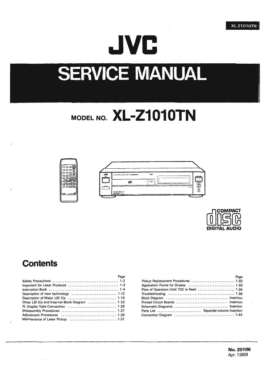
Jvc XLZ 1010 TN Service Manual
This is the 67 pages manual for Jvc XLZ 1010 TN Service Manual.
Read or download the pdf for free. If you want to contribute, please upload pdfs to audioservicemanuals.wetransfer.com.
Extracted text from Jvc XLZ 1010 TN Service Manual (Ocr-read)
Page 1
JVG
Contents
Page
Safety Precautions .......... 1»2
Important for Laser Producrs . . 1-3
insirucrion Book ........ . 1-4
Description of new technology . 1-12
Description of Major LSi ICs . .. .I 1-16
Other LS! ICs and internal Block Diagram 4 123
FL Display Tubs Connection .. . . 1-26
Disassembiy Procedures .. . . 1-27
Adjustment Procedures ..... .. 1-29
Maintenance of Laser Pickup
COM PACT
DIGITAL AUDIO
Pickup Replacement Procedures ......
Appiicarion Points ior Grease . ..
Flow of Operation Umil T00 is Read .I
Troubieshooting .. . . . . . . .
Block Diagram . insenion
Printed Circuit Boards . insertion
Schematic Diagrams . . . insertion
Pans List ........... Separare-volume Insertion
Connecxion Diagram ..... 143
No. 20106
Apr. 1 989
Page 2
XL-z1 o1 OTN
-Safety Precautions
1.
The design of this product contains special hardware and many circuits and components specially for safety pur-
poses. For continued protection, no changes should be made to the original design unless authorized in writing by
the manufacturer. Replacement parts must beidentical to those used in the original circuits. Service should be pen
formed by qualified personnel only.
. Alterations of the design or circuitry of the product should not be made. Any design alterations of the product
should not be made. Any design alterations or additions will void the manufacturer's warranty and will further
relieve the manufacturer of responsibility for personal injury or property damage resulting therefrom
. Many electrical and mechanical parts in the product have special safety-related characteristics. These characteristics
are often not evident from visual inspection nor can the protection afforded by them necessarily be obtained by
using replacement components rated for higher voltage. wattage, etc. Replacement parts Which have these special
safety characteristics are identified in the Parts List of Service Manual. Electrical components having such features
are identified by shading on the schematics and by l A l on the Parts List in the Service Manual. The use of a sub-
stitute replacement which does not have the same safety characteristics as the recommended replacement part shown
in the Parts List of Service Manual may create shock, fire, or other hazards.
. The leads in the products are routed and dressed with ties, clamps, tubings, barriers and the like to be separated from
live parts, high temperature parts, moving parts and/or sharp edges for the prevention of electric shock and fire hazard.
When service is required. the original lead routing and dress should be observed. and it should be confirmed that they
have been returned to normal, after re-assembling.
. Leakage current check l Electrical shock hazard testing)
After re-assembling the product. always perform an isolation check on the exposed metal parts of the product
(antenna terminals, knobs, metal cabinet, screw heads, headphone jack, control shafts, etc.) to be sure the product
is safe to operate without danger of electrical shock.
Do not use a line isolation transformer during this check.
0 Plug the AC line cord directly into the AC outlet. Using a "Leakage Current Tester, measure the leakage current
from each exposed metal part of the cabinet, particularly any exposed metal part having a return path to the
chassis, to a known good earth ground. Any leakage current must not exceed 0.5 mA AC (r.m.s.l.
a Alternate check method
Plug the AC line cord directly into the AC outlet. Use an AC voltmeter having 1,000 ohms per volt or more sensi-
tivity in the following manner. Connect a 1,500 $2 10 W resistor paralleled by a 0.15 F AC-type capacitor be-
tween an exposed metal part and a known good earth ground.
Measure the AC voltage across the resistor with the AC VDLTMETER
AC voltmeter. @ (Having 1000 ohms/volt.
' . or more sensitivi .)
Move the resistor connection to each exposed metal W
c
part, particularly any exposed metal part having a _1
return path to the chassis, and measure the AC voit- 5 c m
age across the resistor. Now, reverse the plug in the " Pl." mu probe
AC outlet and repeat each measurement. Any voltage V on each "pom,
measured must not exceed 0.75 VAC (r.m.s.). This isooo row metal pan.
corresponds to 0.5 mA Ac [r.m.s.). Good rm ground
l
2
3
4
5
rWarning
. This equipment has been designed and manufactured to meet international safety standards.
. It is the legal responsibility of the repairer to ensure that these safety standards are maintained.
. Repairs must be made in accordance with the relevant safety standards.
. it is essential that safety'critical components are replaced by approved parts
. if mains voltage selector is provided, check setting for local voltage.
1-2 (No. 20106)
Page 41
Audio (0/ A and Subsequent)
Turn the power on and
play a disc
Is a signal output N0
(0 P301 (FIX)?
Is a signal output
to P301 (VAL)?
-i
ls MSB adjusted?
i YES
Check that ihere are
no incorrect parts or
poor soldering bet-
ween the D/A con»
vener and the pin
ls performance
satisfactory?
jack.
Playback a track with
em ore-emphasis,
l
Remove (1305 and
care.
l
Does performr
ance conform to
the standard?
Do pins®of
ICSOE and K2306
show the wave-
form?
Do xhe |C303 an n
304 pins show
the specified vol-
Defects around K3303
and "£304,
YES
Is headphone VR
set to MAX?
Sel VR to Max
l'
ls a signal output
to P301 (FIX)?
XL-Z1 01 OTN
To on the next page.
ENN-169«2 headphone
circuit board is defective.
O.K.
YES
Is 0306 collector
aboul -'1 iv?
to 314,
Do pins ® of YES Defectsaround 0306.
K3305 and ICSOS
show lhe wave-
Defects around 6309
and 0310.
Defems around 0.31 1
Belem around IC305 I
and 306 or 0307 and
308.
(
To " on the next page.
No.20106)1-41