Jvc XLF 3000 Service Manual Part 2

This is the 98 pages manual for Jvc XLF 3000 Service Manual Part 2.
Read or download the pdf for free. If you want to contribute, please upload pdfs to audioservicemanuals.wetransfer.com.

Page: 1 / 98
Jvc XLF 3000 Service Manual Part 2

Extracted text from Jvc XLF 3000 Service Manual Part 2 (Ocr-read)


Page 1

TD-F3000

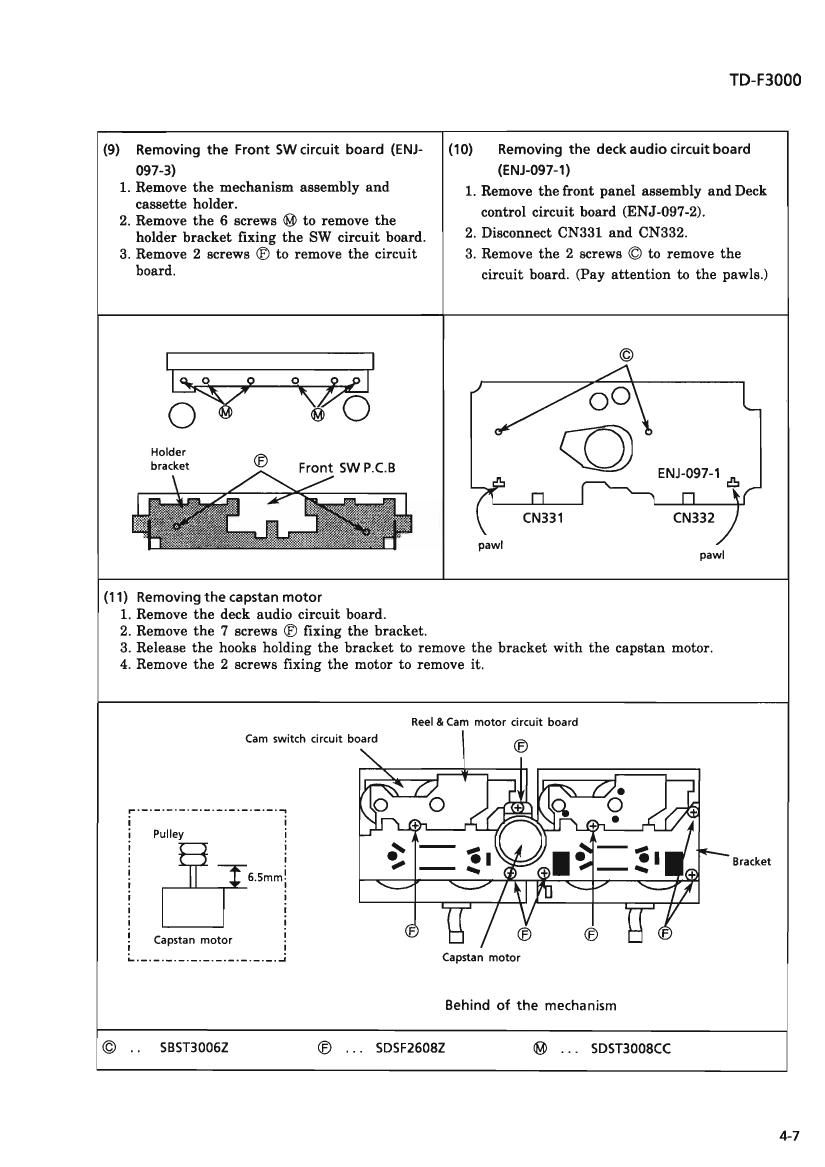
(9) Removing the Front SW circuit board (ENJ-

097-3)

1. Remove the mechanism assembly and
cassette holder.

2. Remove the 6 screws ® to remove the
holder bracket fixing the SW circuit board.

3. Remove 2 screws ® to remove the circuit
board.

(10) Removing the deck audio circuit board

(ENJ-097-1)

1. Remove the front panel assembly and Deck
control circuit board (ENJ-097-2).

2. Disconnect CN331 and CN332.

3. Remove the 2 screws © to remove the

circuit board. (Pay attention to the pawls.)

Front SW P.C.B


ENJ-097-1 flu

pawl

pawl

(11) Removing the capstan motor
1. Remove the deck audio circuit board.
2. Remove the 7 screws ® fixing the bracket

3. Release the hooks holding the bracket to remove the bracket with the capstan motor.
4. Remove the 2 screws fixing the motor to remove it.

Reel &Cam motor circuit board

Cam switch circuit board

,. ....................... _, O
i i
i Pulley i
l !
! ! Bracket
5 6 5mm!
1 I
i i
i i
i i
E Capstan motor :
L ....................... .2 Capstan motor
Behind of the mechanism
© . . SBSTBOOSZ ® SDSFZGOBZ ® . . . SDSTBOOSCC

4-7

Page 2

TD-F3000

(12) Installing the head assembly

The direction of the head is changed with the
head gear. When servicing, install the head
gear according to the direction of the head.

(13) Removing the pinchroller arm assembly

1. Remove the mechanism assembly.

2. Release the hook holding the assembly to
remove it.

Head assembly

Head gear

LL .1
|-rl

Lfi7-l

Head sets FWD mode Head sets REV mode

Pinchroller arm assembly

\l flfii/
i i:

| \

\

Flexible wire

Bottom view of the mechanism

(14) Removing the Flywheels

1. Remove the deck audio circuit board.

2. Remove the 7 screws ® and release the
hooks holding the bracket to remove the
bracket with the capstan motor.

3. Remove the flywheel.

(15) How to install the belts
1. Install the belts as shown in the figure
below.
When putting the belts, put the belt B first.
2. Install the bracket with the capstan motor to
put the belts on the pulleys.

Flywheel Flywheel

A Ji
(.0 y

0 O 0'7
ii ii

Behind of the mechanism

Belt B BeltA

Boss E Boss A

r - -.

: Belt A is longer than B. :

.. _________________ .-

Motor pulley Idler pulley

oi oi
O O

4-8