Jvc UXT 200 R Service Manual

This is the 80 pages manual for Jvc UXT 200 R Service Manual.
Read or download the pdf for free. If you want to contribute, please upload pdfs to audioservicemanuals.wetransfer.com.

Page: 1 / 80
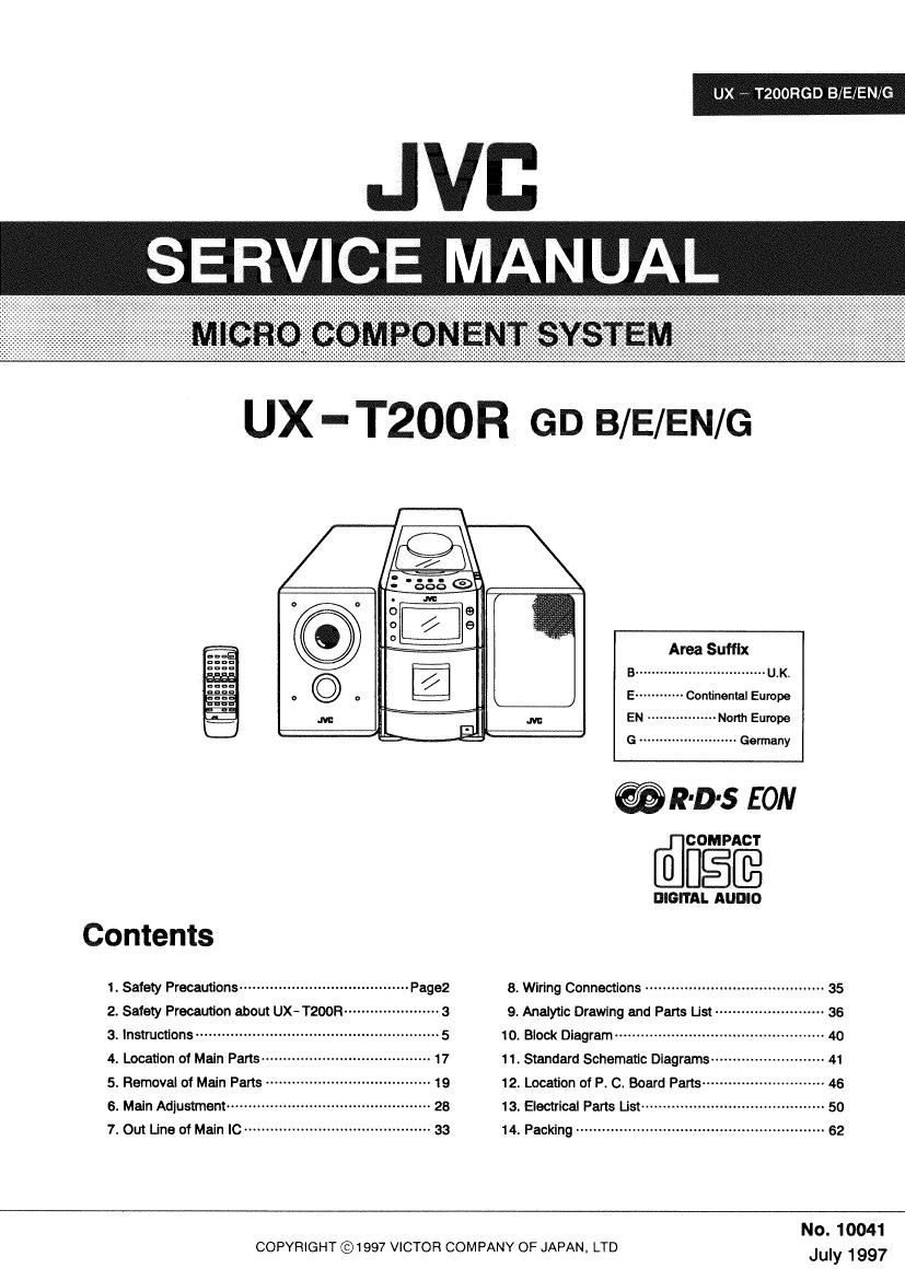
Jvc UXT 200 R Service Manual

Extracted text from Jvc UXT 200 R Service Manual (Ocr-read)


Page 1

UX TZOORGD B/E/EN/G

JVB

SERVICE MANUAL

UX -T200R GD B/E/EN/G

Am Suffix
B ................................ U.K
E ------------ Continental Europe
EN ................. Nonh Europe
G ........................ Germany

@R-D-s EON

mflfigffi

DIGITAL AUDIO
Contents
1 Safety Precautions .................................... Pagaz 8. Wiring Connections ...................................... 35
2. Safety Precaution about UX-T200R ---------------- 3 9. Analytic Drawing and Parts List ---------------------- 36
3. lnstmcflans .......................... 5 10' Block Diagram ................................................ 4o
4. Location of Main Pans~ - 17 11, Standard Schematic DIagrams--- ------ 41
5. Removal of Main Parts 19 12. Location of P. C. Board Parts ----------- 46
6. Main Adlustment --------- 28 13. Electrical Parts List ------------ 50
7. om Line of Main [c ..... 33 14_ Packing ........................... 62
No. 10041

COPYRIGHT ©1997 VICTOR COMPANY OF JAPAN, LTD July 1997

Page 2

UX - TZOORGD B/E/EN/G

1. Safety Precautions

1. The design this product contains speCIal hardware and many circuits and components specially for safety purposes. For continued
protection. no changes should be made to the original design unless authorized in writing by the manufacturer. Replacement parts must
be identical to those used in the original circuits. Service should be performed by qualified personnel only.

2. Alterations of the design or circuitry of the product should not be made. Any design alterations of the product should not be made. Any
design alterations or additions will void the manufactures warranty and will further relieve the manufacture of responsibility for personal
injury or property damage resulting therefrom. I

3. Many electrical and mechanical parts in the product have special safety- related characteristics. These characteristics are often not
evident from visual inspection norcan the protection afforded by them necessarily be obtained by using replacement components rated
for higher voltage. wattage. etc. Replacement parts which have these special safety characteristics are identified in the parts list of
service manual. Electrical components having such features are identified by ( A )on the schematic diagram and parts list in the
service manual. The use of a substitute replacement which does not have the same safety characteristics as the recommended
replacement part shown in the parts list of service manual may create shock. fire. or other hazards.

4. The leads in the products are routed and dressed with ties. clamps . tubings, barriers and the like to be separated from live parts. high
temperature parts, mpving parts and or sharp edges for the prevention of electric shock and fire hazard. When service is required. the
original lead routing and dress should be observed. and it should be confirmed that they have been returned to normal. after
reassembling.

5. Leakage current check (Electrical shock hazard testing)

After re- assembling the product. always perform an isolation check on the exposed metal parts of the product (antenna terminals,

knobs. metal cabinet. screw heads. headphone jack, control shafts. etc.) to be sure the product is safe to operate without danger of

electrical shock. Do not use a line isolation transformer during this check.

~ Plug the AC line cord directly into the AC outlet. using aLeakage current tester". measure the leakage current from each exposed
metal part of the cabinet. particulary any exposed metal part having a return path to the chassis. to a known good earth ground. Any
leakage current must not exposeed 0.5mA AC(r.m.s.)

' Alternate check method

Plug the AC line cord directly into the AC outlet. Use an AC voltmeter E ataxrfi'bgggofigslvolt,
having 1,000 ohms per volt or more sensitivity in the following manner. or more tensltivityJ
Connect a 1.500 ohms 10W resistor paralleled by a 015 ,u F AC type A c i
capacitor between an exposed metal part and a known good earth 0.15 uF AC TYPE
ground. Measure the AC voltage across the resistor with the AC 'l

Place tnls probe
voltmeter. Move the resistor connection to each exposed metal part. a on nah expend

panicularly any exposed metal part having a return path to the chassis. 1500 n 0 W mat-I 0""

and measure the AC voltage across the resistor. Now, reverse the plug Good earth ground

in the AC outlet and repeat each measurement. Any voltage measured

Warning

1. This equipment has been designed and manufactured to meet international safety standards.

2. It is the legal responsibility of the repairer to ensure that these safety standards are maintaintaind.
3. Repairs must be made in accordance with the relevant safety standards.

4. It is essential that safety critical components are replaced by approved parts.

5. If rnains voltage selector is provided. check setting for local voltage.

A CAUTION

Burrs formed during molding may be left over on some parts of the chassis. Therefore, pay attention to
such burrs in the case of preforming repair of this system.

2 (No. 10041)

Page 3

UX - TZOORGD B/EIEN/G

2. Safety Precaution about UX - T200R

IMPORTANT FOR LASER PRODUCTS REPRODUCTION OF LABELS AND

THEIR LOCATION

PRECAUTIONS

1. CLASS 1 LASER PRODUCT

2. DANGER: Invisible laser radiation when open and
interlock failed or defeated. Avoid direct exposure to
beam.

3. CAUTION: Do not open the rear cover. There
are no user serviceable parts inside the unit; leave
all servicing to qualified service personnel.

4. CAU110N: The compact disc player uses invisible
laser radiation and is equipped with safety switches
which prevent the emission of radiation when the CD
holder is open. If is dangerous to defeat the safety
switches,

5. CAUTION: Use of controls for adjustments and the
performanoe of procedures other than those
specified herein may result in exposure to
hazardous radiation.

6.CAUTION: The laser is able to function, if safety
switches out of function. The laser light is invisible.
avoid exposure. do not disassemble the laser unit,
but replace the complete unit.

mmm mmm Wflsyrflgtay- vammiasm
mmmm era-awesome»; mama WWW
minimum! Wait: at mmwér mmmmvfittcmélle
Mm mm amongst-sena- mom. Selma M W Manse
Tom tel Reform (a) WW1 ls) m it)

WARNING:

l

TO REDUCE THE RISK OF FIRE OR ELECTRIC SHOCK, DO
' NOT EXPOSE THIS APPLIANCE TO RAIN 0R MOISTURE.

l

Name/Rating plate

l

i

CAUTION I
F I
l

CAUTION To REDUCE THE RISK OF ELECTRIC SHOCK
DO NOT REMOVE COVER (0R BACK)
No USERSERVICEAELE PARTS INSIDE
REFER SERVICING To QUALIFIED SERVICE PERSONNEL

me Ixfrlmng Iiasn mm slimmest) symbol Wm" an
equilateral mangle. IS Inlehded to aieri me user Io xre
presence (:1 unmsutareu dangerous voltage Within me
orme enclosure that may be 01 sulwem
magnlhfle to constvtole a 1st cl ebxlrlc shock 10
pawns

The exclamawn 90ml mm an equilateral lnlngle ls Caution:

Intended lo aIen the use! to me presence at Imponam - r ' >
BMW and men (New "Wt-ms I" This production contains a laser component of higher
3 °e laser class than Class 1,

(NO. 10041) 3