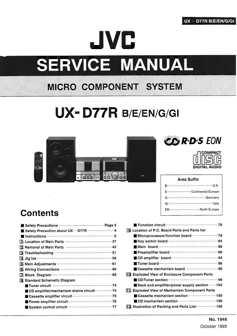
Jvc UXD 77 R Service Manual
This is the 120 pages manual for Jvc UXD 77 R Service Manual.
Read or download the pdf for free. If you want to contribute, please upload pdfs to audioservicemanuals.wetransfer.com.
Extracted text from Jvc UXD 77 R Service Manual (Ocr-read)
Page 1
UX ~ D77R ENfG/Gl
UX- D77R B/E/EN/G/Gl
Contents
I Safety Precautions ....................................... page 2
I Safety Precaution about UX 7 D77R 4
I Instructions ........................................ .. 5
m Locatlon of Maln parts ....................................... 3']
Removal of Main Parts
I3 Traubleshootlng ------------- .
E Jig list ................................................................. 59
[51 Main Adjustments -----
IE Wiring Connections ~
[1 Block Diagram .................................................... 68
[3 Standard Schematic Diagram
I Tuner clrcult .................................................... 74
ICD amplifier/mechanism dralve clrcult~
ICassette amplifier vircuit -
I Power amplifier circuit-~-
IsYstem COhtVO' circuit ....................................... 77
@R-D-s EON
WEE
DIGITAL AUDIO
Area Suffix
B .......................................... Uth
E ---------------------- Continental Europe
G - Germany
Gl .. ........ Italy
EN ----- North Europe
I Function circuit ............................................. 78
[3. Location of P.c. Board Parts and Parts list
I Microprocessor/function board -------------------- 79
I Key switch board
lMain board
I Preamplifier board
I CD amplifier board
I Tuner board -------
I Cassette mechanism board -~
BE Exploded View of Enclosure Component Parts
I CD/Tuner section
I Deck and amplifier/power supply section ~~~~~~ 102
[EL Exploded View of Mechanlsm Component Parts
ICassette mechanism section ----------------------- 105
ICD mechanism section ................................ 105
E2. Illustration of Packing and Parts List --------------- 106
No. 1946
October 1995
Page 2
UX - D77R B/E/EN/G/Gl
1. Safety Precautions
1. The design this product contains special hardware and many circuits and components specially for safety purposes. For continued
protection. no changes should be made to the original design unless authorized in writing by the manufacturer. Replacement parts
must be identical to those used in the original circuits. Service should be performed by qualified personnel only.
2. Alterations of the design or circuitry of the product should not be made. Any design alterations of the product should not be made.
Any design alterations or additions will void the manufacture's warranty and will further relieve the manufacture of responsibility
for personal injury or property damage resulting therefrom.
3. Many electrical and mechanical parts in the product have special safety - related characteristics. These characteristics are often
not evident from visual inspection nor can the protection afforded by them necessarily be obtained by using replacement
components rated for higher voltage. wattage. etc. Replacement parts which have these special safety characteristics are
identified in the parts list of service manual. Electrical components having such features are identified by shadinguE) and (A)
on the schematic diagram and parts list in the service manual. The use of a substitute replacement which does not have the same
safety characteristics as the recommended replacement part shown in the pans list of service manual may create shock. fire. or
other hazards.
4. The leads in the products are routed and dressed with ties. clamps . tubings. barriers and the like to be separated from live pans.
high temperature parts. mpving parts and or sharp edges for the prevention of electric shock and fire hazard. When service is
required. the original lead routing and dress should be observed. and it should be confirmed that they have been returned to
normal. after reassembling.
5. Leakage current check (Electrical shock hazard testing)
After re - assembling the product. always perform an isolation check on the exposed metal pans of the product (antenna
terminals. knobs. metal cabinet. screw heads. headphone jack. control shafts, etc.) to be sure the product is safe to operate
without danger of electrical shock. Do not use a line isolation
transformer during this check.
- Plug the AC line cord directly into the AC outlet. using aLeakage
current tester". measure the leakage current from each exposed
metal part of the cabinet. particulary any exposed metal part
having a return path to the chassis. to a known good earth ground.
Any leakage current must not exposeed 0.5mA AC(r.m.s.)
~ Alternate check method
Plug the AC line cord directly into the Ac outlet. Use an AC
voltmeter having 1,000 ohms per volt or more sensitivity in the following manner. Connect a 1.500 ohms 10W resistor paralleled
by a 015 ,u F AC type capacitor between an exposed metal part and a known good earth ground. Measure the AC voltage
across the resistor with the AC voltmeter. Move the resistor connection to each exposed metal part, particularly any exposed
metal part having a return path to the chassis, and measure the AC voltage across the resistor. Now. reverse the plug in the AC
outlet and repeat each measurement. Any voltage measured must not exceed 0,75V AC(r.m.s.).This corresponds to 0.5mA
AC(r.m.s.).
warning ' (UK ONLW
1. This equipment has been designed and manufactured to meet international safety standards.
2. it is the legal responsibility of the repairer to ensure that these safety standards are maintaintaind.
3. Repairs must be made in accordance with the relevantsafety standards.
4. it is essential that safety critical components are replaced by approved parts.
5. if mains voltage selector is provided. check setting for local voltage.
2 (No.1946 )
Page 15
(SWITCHING THE POWER ON/OFF
new GOMPDNEM SYSTEM uxrumz
O
66.?
mm obs-moss
nit-um
'5
0
co
L.
*r I I
I-_l
I i i
TUNER button
UX - D77R B/E/EN/G/Gl
f-_L
we 7 JV:
// //
POWER button
mm mm; mm cowoNENstsiEM wanna
Play/pause (i> ll) button
Play (<1, i>) buttons MD/AUX button
Switching the power onloff
0 Switching on:
POWER
0 The indicator in the display window lights.
a STANDBY
0 Switching oft:
POWER
{éi-S'rmnav
The indicator goes out.
The indicator lights.
0 The Indicator in the display window goes out and only the clock is
Indicated.
(No. 1946) 15
Page 33
UX - D77R B/E/EN/G/Gl
0 Select the TIMER mode.
0 The selected timer mode is shown in the display.
El
4 5 2
Q6 Q? TU;ER -} TUNER REC -> CD -} TAPE .- [:> L 7.K_
_I I
_ _/ I_ / l \
1 While pressing the SHIFT button.
When the UP button is pressed to select the timer mode, the
mode changes lrom TUNER (timer reception at a broadcast),
to TUNER/REC (timer recording 01 a broadcast), to CD (timer
play 01 a CD), to TAPE (timer playback ol a tape), in this
order.
0 Set the volume.
III-II _ , l/III l-l , III-ll I Ill-ll I:
V LIL II /_IL L! l/ I_Il_ I 11 /_Il_ _I
When the UP button is used to select the volume. . 1:22;?35; [3335:3133fizmwgfmceoyng;rfi$b automatically
VOLUME
MIN MAX
This shows when volume level 1 is selected. 0 The selected volume is set,
0 The unit enters Ihe previously engaged mode and timer setting
has been completed.
0 When the volume setting is set to "VOL - (volume level
is not specified), the timer playback volume is at the level
used before setting the timer.
0 To confirm the timer setting Notes:
1. Each time the (6)) TIMER button is pressed while 0 When the timer is set incorrectly or the correct mode is
pressing the SHlFT button, the timer setting can be not selected, perform "Setting the timer" from the
confirmed. beginning,
2. When the previously engaged mode is displayed, timer 0 When the timer is se , "-:«-" in the display is replaced by
setting has been completed. the input digits,
0 When the timer stop time is not set, the timer operates
for 2 hours and then the unit is switched off.
(No. 1946) 33
Page 34
UX - D77R B/EIEN/GIGI
Timer recording of broadcast
OThe current time must be set before the timer can be
used.
0 Make sure that the safety tabs of the cassette have not
been broken off.
Operations
JVI:
//
wro REVERSE
//
wear: COMPONENY SVSYEM uxona
I
l
l
mac comment 5mm UX-DWR
mm m
mm mm
was
am most
330 .8.
€35 €35 .
0 Set the POWER button to ON.
0 Load a cassette.
0 Insert the cassette with the side to be recorded facing
out.
0 Set the reverse mode button to
set the DOLBY NR button as required.
L_-J i__i
i; i;
or " 3) " and
0 Set the timer. (Refer to "Setting the timer" on page 45.)
0 Set the timer about a minute before the broadcast to
be recorded is scheduled to start.
0 Tune to the station to be recorded. (Refer to page 29.)
9 Set the POWER button to STANDBY.
I Timer recording will start at timer start time and the
power will be switched off at timer stop time. (The
timer mode is then released.)
0 To cancel timer operation
Press the timer (9)) ON/OFF button while pressing the
SHIFT button so that the timer mode indicator (0) goes
out.
If you do this, timer recording will not start at the timer start
time.
Notes:
Once the timer has been set, the start and stop times, etc.,
are stored in memory. When timer recording or playback is
required at different times, the timer must be set again.
0 After setting the timer start and stop times, check that the
tuner is tuned to the required frequency.
0 When the power cord is disconnected or there is a power
failure, timer settings will be erased from memory. If this
happens, set the current time and periorm the timer
setting again.
34 (No. 1946)
mom ,opm
i o o l 0 CLOSE
msimcrim mum pm
DOWN U PRESEV YUNER
« .. t. a...
m. . . .
C") ii Ci 6
as.
D SRO'SEON
mm...
Lia C