Jvc THC 7 Service Manual

This is the 72 pages manual for Jvc THC 7 Service Manual.
Read or download the pdf for free. If you want to contribute, please upload pdfs to audioservicemanuals.wetransfer.com.

Page: 1 / 72
Jvc THC 7 Service Manual

Extracted text from Jvc THC 7 Service Manual (Ocr-read)


Page 1

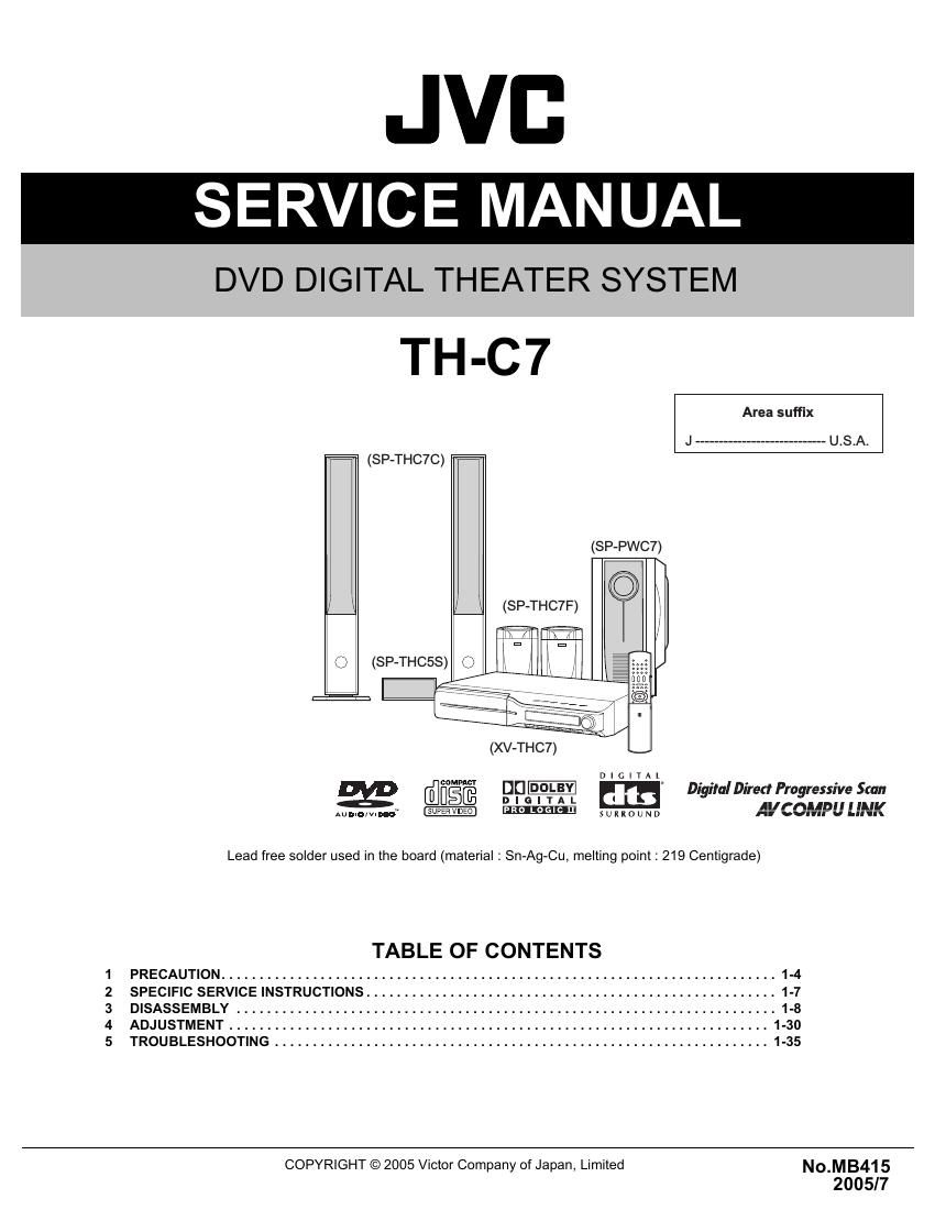
JVC

SERVICE MANUAL

DVD DIGITAL THEATER SYSTEM

TH-C7

Area suffix

J ............................ U.S.A.

(SP-THC7C)

(SP-PWC7)

» \ (SP-THC7F)

Q (SP-THCSS)

I:

(XV~THC7)

D I a I T A L
mum/w. _UPERvao PR0 LOGIC n mmmu AVCOMPU LINK

E @figfi Dfl- Em Digital Direrr Progressive Scan

Lead free solder used in the board (material : Sn-Ag-Cu, melting point 1 219 Centigrade)

TABLE OF CONTENTS

1 PRECAUTION ......................................................................... 1-4
2 SPECIFIC SERVICE INSTRUCTIONS. . ........................ 1-7
3 DISASSEMBLY ........................................... 1-8
4 ADJUSTMENT ................................. 1-30
5 TROUBLESHOOTING ................................................................. 1-35
COPYRIGHT © 2005 Victor Company of Japan, Limited No_MB415

2005/7

Page 2

SPECIFICATION

Center unit (XV-THC7)

Audio section Total Harmonic Distortion *1 0.02%
Digital input *2 DIGITAL IN (DBS) - 21 dBm to - 15 dBm
(OPTICAL) (660 nm :30 nm)
Video section Video System NTSC
Horizontal Resolution 500 lines
Signal-to-Noise Ratio 64 dB
Video output level Composite 1.0 V(p-p)/75 £2
S-video-Y 1.0 V(p-p)/75 £2
S-video-C 0.286 V(p-p)/75 £2
Component-Y 1.0 V(p-p)/75 £2
Component-PB/PR 0.7 V(p-p)/75 (2
Video input sensitivity/ Composite 1.0 V(p-p)/75 £2
'mpedance (VCR 'N) S-video-Y 1.0 V(p-p)/75 :2
S-video-C 0.286 V(p-p)/75 £2
Tuner section Tuning Range FM 87.5 MHz to 108.0 MHz
AM 530 kHz to 1 710 kHz
General Power Requirements AC 120 V . 60 Hz
Power Consumption 16 W (at operation)
1.3 W (in standby mode)
Dimensions (W X H X D) 400 mm x 85 mm x 399 mm(15-3l4 inches X 3-3/8 inches >< 15-3/4 inches)
Mass 4.2 kg (9.3 lbs)

*1: This value is measured at System cord CONNECTOR for reference.

*2: Corresponding to Linear PCM, Dolby Digital, and DTS Digital Surround (with sampling frequency -32 kHz, 44.1 kHz, 48 kHz)

Subwoofer (SP-PWC7)

Amplifier section FrontJCenter/Surround 167 W per channel, RMS at 3 Q at 1kHz, with 10 % total harmonic distortion.

Subwoofer 167 W, RMS at 3 Q at 100 Hz. with 10 % total harmonic distortion.

Speaker section Speaker unit 25 cm (9-7/8 inches) Bass-reflex

Power Handling Capacity 170 W

Impedance 3 9

Frequency Range 25 Hz to 200 Hz
General Power Requirements AC 120 V, 60 Hz

Power Consumption 160 W (at operation)

0 W (in standby mode)

Dimensions (W X H x D) 264 mm X 481 mm X 459 mm(10-7/16 inches x 18-15/16 inches ><18-1/8 inches)

Mass 16.5 kg (37 lbs)

1-2 (No.MB415)

Page 20

3.3.7 Removing the DVD pickup
(See Figs.12 to 14)
- Remove the tray assemblies, DVD servo board and DVD
traverse mechanism assembly.

(1) From the top side of the DVD traverse mechanism assem-
bly, release the lock of the connector on the DVD pickup
and disconnect the card wire in the direction of the arrow.
(See Fig.12.)

(2) Turn the screw shaft gear in the direction of the arrow 1 to
move the DVD pickup in the direction of the arrow 2. (See
Fig.12.)

(3) Remove the screw G attaching the feed bracket and re-
move the feed bracket from the sections k. (See Fig.12.)

(4) Release the claw m of the thrust spring in the direction of
the arrow and remove the thrust spring. (See Fig.12.)

(5) Remove the guide shaft from the sections (n, p) on the
C.TM chassis. (See Fig.13.)

(6) Remove the section q of the DVD pickup. (See Fig.13.)

(7) Remove the two screws H attaching the rack arm spring
and rack arm. (See Fig.14.)

(8) Pull the guide shaft from the DVD pickup in the direction of
the arrow. (See Fig.14.)

3.3.8 Attaching the DVD pickup
(See Figs.12 to 14)

(1) Attach the guide shaft to the DVD pickup and attach the
rack arm spring and rack arm with the screws H. (See
Fig.14.)

(2) Attach the section q of the DVD pickup to the C.TM chassis
first and attach the guide shaft to the sections (n, p). (See
Fig.13.)

Reference:
When attaching the guide shaft to the section p, attach it
under the rod spring. (See Fig.13.)

(3) Attach the thrust spring and feed bracket with the screw G.
(See Fig.12.)

(4) Turn the screw shaft gear in the direction of the arrow 1 to
move the DVD pickup in the direction of the arrow 2. (See
Fig.15.)

(5) Connect the card wire to the connector on the DVD pickup.
(See Fig.15.)

1-20 (No.MB415)

DVD traverse mechanism assembly
Feed bracket


Thrust spring
Connector

DVD pickup

Fig.12
DVD pickup q

Rod spring Guide Shaft

C.TM chassis
Fig.13

Page 31

5.FORCED NTSC MODE
It is made compulsive NTSC mode.
From this, with regards to the input of NTSEL_SW, there is nothing only
at the time of 1st power on, and it performs NTSC starting.
(Command specification is performed to a module.)
A mode clearance is performed by power off.
VIDEO FORMAT change is prohibited during Forced NTSC mode.

Insert the power cord in an outlet while
pressing the "POWER" and "PAUSE" keys
on the main unit simultaneously.

I

A main unit entered in the
NTSC mode compulsively.

6.TRAY LOCK
A leader mechanism's tray lock is carried out. In the tray lock function ON state,
EJECT processing is not performed to the EJECT key.
And , a LOCK display is performed at this time.
When it turns off a tray lock function, STOP and EJECT KEY are pushed simultaneously again.
Back up ON/OFF of a tray lock.

Press the "STOP and "OPENICLOSE1" keys
on the remote controller at standby.

A tray lock is completed.

4.1.3 Upgrading of firmware (DVD UPGRADE)
The latest firmware for upgrading is updated in Optical disc CSG" page in JS-net. At the time of service, compare the version of the
product and the latest version, and upgrade the old version into the latest version.

(1) Press "STANDBY/ON" key of the main body to turn it on.

(2) Push OPEN/CLOSE" key of the main body. and insert the upgrade disc in the tray.

(3) When reading the data of the disc, the OSD screen is displayed "VERSION UP DISC", "PROGRAM & DESTINATION MODE"

and "READING...

(4) When the screen changes from READING." to "WRITING..", upgrading starts.

(5) After writing the data of the disc, the screen is displayed "OPEN".

(6) Take out the disc, and press "STANDBY/ON" key of the main body.

(7) When the stand-by indicator is lighted, upgrading is completed.

(8) Set the main body at test mode, and confirm the version of the firmware. (Refer to "4.2 Method of displaying version firmware".)

4.1.4 Upgrading of system microcomputer (ROM CORRECTION)

(1) Press "STANDBY/ON" key of the main body to turn it on.

(2) Push "OPEN/CLOSE" key of the main body, and insert the upgrade disc in the tray.

(3) When reading the data of the disc, the OSD screen is displayed "VERSION UP DISC", "SYSCON UPG MODE" and "READ-
ING..".

(4) When the screen changes from READING." to "WRITING..", system data is written.

(5) After writing the data of the disc, the FL display of the main body is displayed "COMPLETE".

(6) Take out the disc, and press "STANDBY/ON" key of the main body.

(7) When the stand-by indicator is lighted, upgrading is completed.

(8) Set the main body at test mode, and confirm the version of the system microcomputer. (Refer to "4.2 Method of displaying ver-
sion firmware".)

(No.MB415)1-31