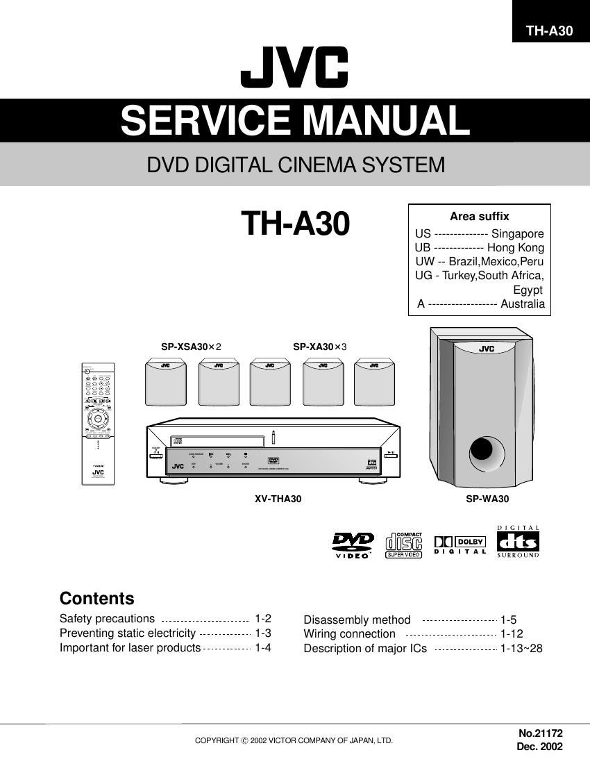
Jvc THA 30 Service Manual
This is the 67 pages manual for Jvc THA 30 Service Manual.
Read or download the pdf for free. If you want to contribute, please upload pdfs to audioservicemanuals.wetransfer.com.
Extracted text from Jvc THA 30 Service Manual (Ocr-read)
Page 1
TH-A30
JVB
SERVICE MANUAL
DVD DIGITAL CINEMA SYSTEM
TH A30 Area suffix
- US ______________ Singapore
UB - Hong Kong
UW - Brazil,Mexico,Peru
UG - Turkey,South Africa,
Egypt
A - Australia
SP-XSA30X 2 SP-XA30x3
fit-tfi: E
mar: m JVI: '2' o M 0 j .._..-..M.. (as; 1:
JV}:
DJ; 1: V ,1
XV-THA30 SP-WA30
1) | G | T A L
wrote 00- Em
VIDEO" I: I G I T A " SURROUND
Contents
Safety precautions - 1-2 Disassembly method ................... 1-5
Preventing static electricity -------------- 1-3 Wiring connection ........................ 1-12
Important for laser products ------------- 1-4 Description of major [05 ---------------- 1-13~28
No.21172
COPYRIGHT (c) 2002 VICTOR COMPANY OF JAPAN, LTD.
Dec. 2002
Page 2
TH-A3O
-Safety Precautions
1. This design of this product contains special hardware and many circuits and components specially for safety
purposes. For continued protection, no changes should be made to the original design unless authorized in
writing by the manufacturer. Replacement parts must be identical to those used in the original circuits. Services
should be performed by qualified personnel only.
2. Alterations of the design or circuitry of the product should not be made. Any design alterations of the product
should not be made. Any design alterations or additions will void the manufacturers warranty and will further
relieve the manufacture of responsibility for personal injury or property damage resulting therefrom.
3. Many electrical and mechanical parts in the products have special safety-related characteristics. These
characteristics are often not evident from visual inspection nor can the protection afforded by them necessarily
be obtained by using replacement components rated for higher voltage, wattage, etc. Replacement parts which
have these special safety characteristics are identified in the Parts List of Service Manual. Electrical
components having such features are identified by shading on the schematics and by (Q) on the Parts List in
the Service Manual. The use of a substitute replacement which does not have the same safety characteristics
as the recommended replacement parts shown in the Parts List of Service Manual may create shock, fire, or
other hazards.
4. The leads in the products are routed and dressed with ties, clamps, tubings, barriers and the like to be
separated from live parts, high temperature parts, moving parts and/or sharp edges for the prevention of
electric shock and fire hazard. When service is required, the original lead routing and dress should be
observed, and it should be confirmed that they have been returned to normal, after re-assembling.
5. Leakage currnet check (Electrical shock hazard testing)
After re-assembling the product, always perform an isolation check on the exposed metal parts of the product
(antenna terminals, knobs, metal cabinet, screw heads, headphone jack, control shafts, etc.) to be sure the
product is safe to operate without danger of electrical shock.
Do not use a line isolation transformer during this check.
0 Plug the AC line cord directly into the AC outlet. Using a "Leakage Current Tester", measure the leakage
current from each exposed metal parts of the cabinet, particularly any exposed metal part having a return
path to the chassis, to a known good earth ground. Any leakage current must not exceed 0.5mA AC (r.m.s.).
0 Alternate check method
Plug the AC line cord directly into the AC outlet. Use an AC voltmeter having, 1,000 ohms per volt or more
sensitivity in the following manner. Connect a 1,500 Q 10W resistor paralleled by a 0.1511 F AC-type capacitor
between an exposed metal part and a known good earth ground. AC VOLTMETER
Measure the AC voltage across the resistor with the AC a (HavingiOOO
vo|tmeter_ ohms/volts, .. .
Move the resistor connection to each exposed metal part, a c (more sens't'v'ty)
particularly any exposed metal part having a return path to
the chassis, and meausre the AC voltage across the resistor. 015: AC TYPE
Now, reverse the plug in the AC outlet and repeat each -| Placethis
measurement. Voltage measured any must not exceed 0.75 V W» . Sgifieeigosed
AC (r.m.s.). This corresponds to 0.5 mA AC (r.m.s.). 15009 10W metal part.
Good earth ground
_ Warning A CAUTION
1.This equipment has been designed and manufactured to meet international safety standards. Burrs formed during molding may
2. it is the legal responsibility of the repairer to ensure that these safety standards are maintained. be left over on some parts of the
3. Repairs must be made in accordance with the relevant safety standards.
4. it is essential that safety critical components are replaced by approved parts. such burrs in the case of
5. if mains voltage selector is provided, check setting for local voltage. preforming repair of this system.
chassis. Therefore, pay attention to
In regard with component parts appearing on the silkscreen printed side (parts side) of the PWB diagrams, the
parts that are printed over with black such as the resistor (I), diode (-) and ICP (Q) or identified by the "A"
mark nearby are critical for safety.
(This regulation does not correspond to J and C version.)
1-2
Page 53
TH-A30
l Electrical parts list (Main&iack board) Block No. 01
A llem Pans number Paris name Remarks Area Item Paris number Parts name Remarks Area
O31ER 05027001043 POWERTRANSISTOR KSOIS91 R127 20077000572 CHIP RESISTOR 220 5% 1/10W
O31 RL 05027001043 POWER TRANSISTOR KSOIS91 R13 20077000292 CHIP RESISTOR 100K 5% 1/10W
O31 RR 05027001049 POWER TRANSISTOR KSOIS91 R131 20077000572 CHIP RESISTOR 220 5% 1/10W
031W 05037001014 ORT TRANSISTOR 25D24957F R134 20077000572 CHIP RESISTOR 220 5% 1/10W
O32C 05027001210 POWER TRANSISTOR I
O32ER 05027001210 POWER TRANSISTOR KSBI151 R139W 20077000459 CHIP RESISTOR 1K 5% wow
032RL 05027001210 POWER TRANSISTOR KSBI151 R14 20077000930 CHIP RESISTOR 39K 5% 1/10W
032RR 05027001210 POWER TRANSISTOR KSSI151 RM? 20077000586 CHIP RESISTOR 22K 5% 1/10W
O32W 05037001010 ORT TRANSISTOR 2551526? RMS 20077000586 CHIP RESISTOR 22K 5% 1/10W
033W 05037001016 ORT TRANSISTOR 2SB1520P R15 20077000941 CHIP RESISTOR 47K 5% 1/10w
O34C 05027001210 POWER TRANSISTOR I
O34ER 05027001210 POWER TRANSISTOR KSBI151 R19 20077000774 CHIP RESISTOR 33K 5% 1/10W
QBARL 05027001210 POWER TRANSISTOR I
034W 05037001010 ORT TRANSISTOR ZSBEZBVF R200R 20077000595 CHIP RESISTOR 3.3K 5% 1/10W
O350 05017000393 TRANSISTOR KS0945 R201L 20077000774 CHIP RESISTOR 33K 5% 1/10W
O35EL 05015000398 TRANSISTOR I
QBSRL 05017000399 TRANSISTOR KS0945 R22 20077000586 CHIP RESISTOR 22K 5% 1/10W
O35RR 05017000399 TRANSISTOR KS0945 R30W 20077000941 CHIP RESISTOR 47K 5% 1/10W
035W 05017000331 TRANSISTOR KSCIODSVV R31W 20077000686 CHIP RESISTOR 3,3K 5% 1/10W
anc 05027001043 POWER TRANSISTOR KSOIS91 R320 20077000493 CHIP RESISTOR 2,2K 5% 1/10W
QBSFL 05027001043 POWER TRANSISTOR KSDIS91 R32EL 20077000493 CHIP RESISTOR 2,2I< 5% 1/10W
O3SER 05027001043 POWER TRANSISTOR KSOIS91 R32ER 20077000493 CHIP RESISTOR 2,2K 5% 1/10W
QHBRL 05027001049 POWER TRANSISTOR KSOIS91 R32RL 20077000493 CHIP RESISTOR 2,2K 5% 1/10W
OasRR 05027001043 POWER TRANSISTOR KSOIS91 R32RR 20077000493 CHIP RESISTOR 2,2K 5% 1/10W
Oasw 05027001049 POWER TRANSISTOR KSOIS91 R32W 20077000241 CHIP RESISTOR 1,5I< 5% 1/10W
O37 05047000150 OICI TRANSISTOR I
040 05027000299 POWER TRANSISTOR I
05 0501000510 TRANSISTOR KSAQZBAVV R34ER 20077000401 CHIP RESISTOR 150 5% 1/10W
O7 05017000314 TRANSISTOR I
O9 05017000010 TRANSISTOR KSCIQOS R34W 20077000290 CHIP RESISTOR 100 5% 1/10W
A REI 35017001214 REALY 12v 0,45W R350 20077000493 CHIP RESISTOR 2,2I< 5% 1/10W
A RE2 35017001214 REALV 12v 0.45W W R35EL 20077000493 CHIP RESISTOR 2,2K 5% 1/10W
A RE3 35017001003 REALv 12VOC 530MW 10A R35ER 20077000493 CHIP RESISTOR 2,2K 5% 1/10W
A REA 35017001003 REALY 12VOC 530MW10A W R35RL 20077000493 CHIP RESISTOR 2,2K 5% 1/10W
RE5 35017001197 RELAv I2VOC 0.54W R35RR 20077000493 CHIP RESISTOR 2,2I< 5% 1/10W
RES 35017001197 RELAY I2VOC 0.54W R35W 20077000241 CHIP RESISTOR 1,5K 5% 1/10W
RE7 35017001197 RELAv 12VOC 0,54W R360 20017000522 CARBON RESISTOR 22K 5% 1I9W
RS01W 20077000300 CHIP RESISTOR 10K 5% wow R30EL 20077000586 CHIP RESISTOR 22K 5% 1/10W
RS02W 20077000300 CHIP RESISTOR 10K 5% wow RasER 20017000522 CARBON RESISTOR 22K 5% 1/9W
R10 20077000292 CHIP RESISTOR 100K 5% 1/10W R30RL 20077000586 CHIP RESISTOR 22K 5% 1/10W
R105 20077000572 CHIP RESISTOR 220 5% mow R3eRR 20017000522 CARBON RESISTOR 22K 5% 1/9W
R109 20077000941 CHIP RESISTOR 47K 5%1/10W R30W 20077000553 CHIP RESISTOR 27K 5% 1/10W
R113 20077000941 CHIP RESISTOR 47K 5%1/10W R370 20077000401 CHIP RESISTOR 150 5% 1I10W
R1140 20017000515 CARBON RESISTOR 220 5% new R37EL 20077000401 CHIP RESISTOR 150 5% 1/10W
R114W 20017000515 CARBON RESISTOR 220 5% new R37ER 20077000401 CHIP RESISTOR 150 5% 1/10W
R11ew 20077000572 CHIP RESISTOR 220 5% mow R37RL 20077000401 CHIP RESISTOR 150 5% 1/10W
R1170 20077000409 CHIP RESISTOR IK 5% 1/10w R37RR 20077000401 CHIP RESISTOR 150 5% 1/10W
R117W 20077000493 CHIP RESISTOR 2.2K 5% 1/10w R37W 20077000290 CHIP RESISTOR 100 5% 1/10W
R1 150 20077000300 CHIP RESISTOR 10K 5%1/10W R38 20037000710 OMP RESISTOR 47 5% 2W
R1 13W 20077000300 CHIP RESISTOR 10K 5% wow RSSC 20077001039 CHIP RESISTOR 56K 5% 1/10W
R119W 20077000941 CHIP RESISTOR 47K 5% wow R39EL 20077001039 CHIP RESISTOR 56K 5% 1/10W
R12 20077000595 CHIP RESISTOR 22K 5% wow R39ER 20077001039 CHIP RESISTOR 56K 5% 1/10W
3»9