Jvc THA 10 Service Manual

This is the 128 pages manual for Jvc THA 10 Service Manual.
Read or download the pdf for free. If you want to contribute, please upload pdfs to audioservicemanuals.wetransfer.com.

Page: 1 / 128
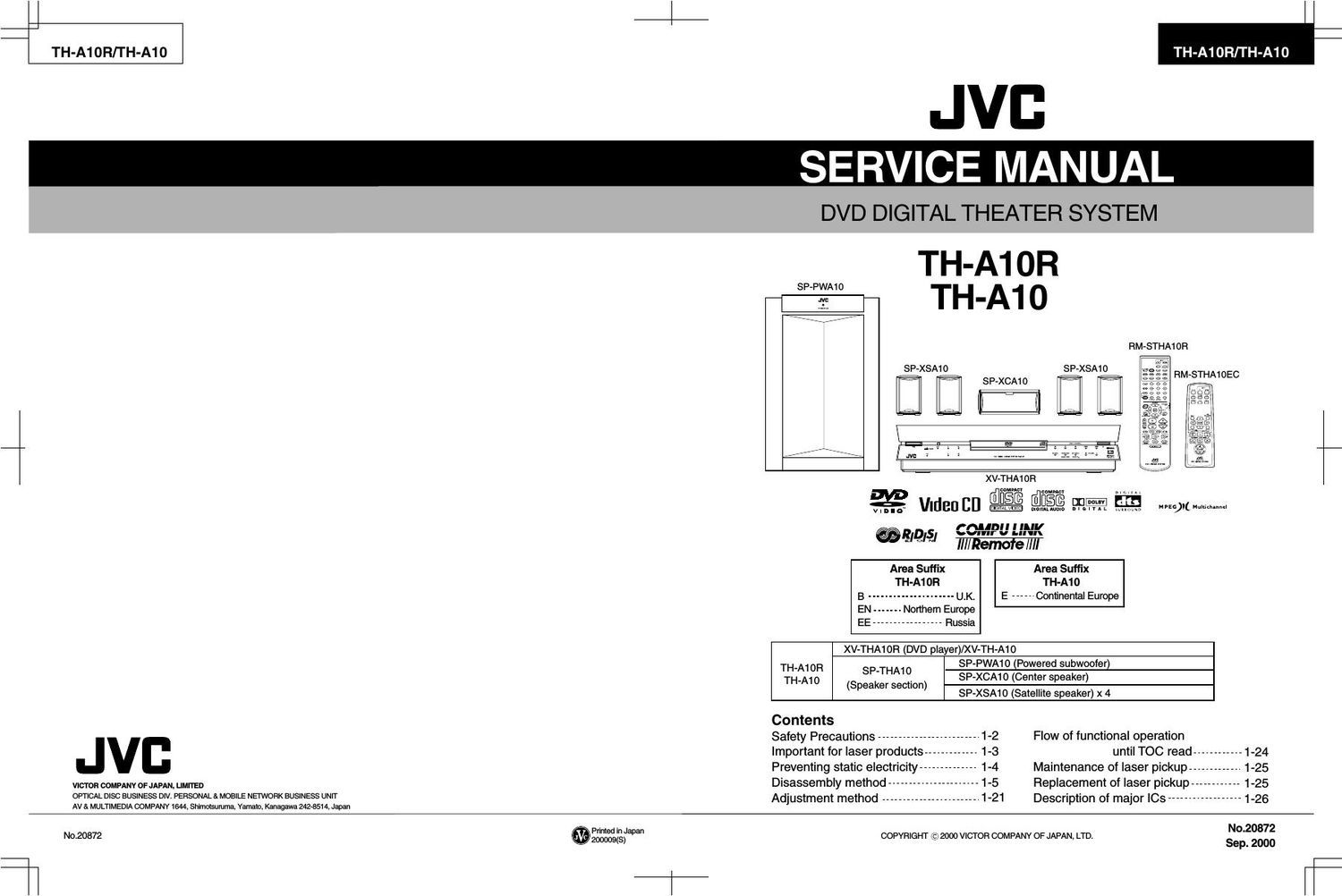
Jvc THA 10 Service Manual

Extracted text from Jvc THA 10 Service Manual (Ocr-read)


Page 1

TH-A10R/TH-A10

TH-A10R/TH-A10

JVB

SERVICE MANUAL

DVD DIGITAL THEATER SYSTEM

TH-A1OR

SP-PWAIO

SP-XSA10

TH-A1O

RM-STHAIOFI


SP- XSA10

XV- THA10R

a: VIEIBU E[I_ EEEE EiEE un- ELI!

_EM IDEU DIGIYALAUDIO n | a | v A L wmumi MPEG)( Nuk'd'me'

ffillbl I I ll",

M STHAIOEC

@RIDISI \onnr v Llll
E Q III/Remofe /III
Area Suffix Area Suffix
TH-A10R TH-A10
B --------------------- U.K. E ------ Continental Europe
EN - Northern Europe
EE ----------------- Russia
XV-THAIOFI (DVD pla er)/XV-TH-A1O
SP-PWA10 (Powered Subwoofer)
TH-A1OR _
TH-A1O SP THA10_ SP-XCA10 (Center speaker)
(Speaker sectIon) ,
SP-XSA10 (Satelllte Speaker) x 4
Contents
Safety Precautions ------------------------- 1-2 Flow of functional operation
v Important for laser products ------------- 1-3 until TOC read ------------ 1-24
Preventing static electricity -------------- 1-4 Maintenance of laser pickup ------------ 1-25
V'CTOR COMPANV OFMPANI LIMITED Disassembly method ---------------------- 1-5 Replacement of laser pickup ............ 1.25
OPTICAL Disc BUSINESS DIV. PERSONAL& MOBILE NETWORK BUSINESS UNIT Adjustment method ________________________ 1.21 Description Of major ICS __________________ 1-26
AV & MULTIMEDIA COMPANY 1644, Shimotsuruma, Yamato, Kanagawa 242-8514, Japan
No.20872 .Smgfapa COPYRIGHT (c) 2000 VICTOR COMPANY OF JAPAN, LTD. 3:62:33:

f

Page 2

TH-A1OR/TH-A10

-Safety precautions

1.

2.

This design of this product contains special hardware and many circuits and components specially
for safety purposes. For continued protection, no changes should be made to the original design
unless authorized in writing by the manufacturer. Replacement parts must be identical to those
used in the original circuits. Services should be performed by qualified personnel only.

Alterations of the design or circuitry of the product should not be made. Any design alterations of
the product should not be made. Any design alterations or additions will void the manufacturers
warranty and will further relieve the manufacture of responsibility for personal injury or property
damage resulting therefrom.

.Many electrical and mechanical parts in the products have special safety-related characteristics.

These characteristics are often not evident from visual inspection nor can the protection afforded
by them necessarily be obtained by using replacement components rated for higher voltage,
wattage, etc. Replacement parts which have these special safety characteristics are identified in
the Parts List of Service Manual. Electrical components having such features are identified by
shading on the schematics and by (Q) on the Parts List in the Service Manual. The use of a
substitute replacement which does not have the same safety characteristics as the recommended
replacement parts shown in the Parts List of Service Manual may create shock, fire, or other
hazards.

.The leads in the products are routed and dressed with ties, clamps, tubings, barriers and the

like to be separated from live parts, high temperature parts, moving parts and/or sharp edges
for the prevention of electric shock and fire hazard. When service is required, the original lead
routing and dress should be observed, and it should be confirmed that they have been returned
to normal, after re-assembling.

.Leakage currnet check (Electrical shock hazard testing)

After re-assembling the product, always perform an isolation check on the exposed metal parts
of the product (antenna terminals, knobs, metal cabinet, screw heads, headphone jack, control
shafts, etc.) to be sure the product is safe to operate without danger of electrical shock.

Do not use a line isolation transformer during this check.

0 Plug the AC line cord directly into the AC outlet. Using a "Leakage Current Tester", measure
the leakage current from each exposed metal parts of the cabinet, particularly any exposed
metal part having a return path to the chassis, to a known good earth ground. Any leakage
current must not exceed 0.5mA AC (r.m.s.)

0 Alternate check method
Plug the AC line cord directly into the AC outlet. Use an AC voltmeter having, 1,000 ohms
per volt or more sensitivity in the following manner. Connect a 1,5009 10W resistor paralleled by
a 0.15uF AC-type capacitor between an exposed

AC VOLTMETER
metal part and a known good earth ground. (Having 1000
Measure the AC voltage across the resistor with the ' 7 ohms/volts,
AC voltmeter. or more sensitivity)
Move the resistor connection to eachexposed metal ° °
part, particularly any exposed metal part having a 0_15,uF AC TYPE
return path to the chassis, and meausre the AC _"_ Place this
voltage across the reSIstor. Now, reverse the plug In probe on
the AC outlet and repeat each measurement. voltage 'WV > each exposed
measured Any must not exceed 0.75V AC (r.m.s.). 15009 10W metal part.

This corresponds to 0.5 mA AC (r.m.s.).
Good earth ground

-Warning
1.
2.
3.
4.
5.

This equipment has been designed and manufactured to meet international safety standards.

It is the legal responsibility of the repairer to ensure that these safety standards are maintained.
Repairs must be made in accordance with the relevant safety standards.

It is essential that safety critical components are replaced by approved parts.

If mains voltage selector is provided, check setting for local voltage.

A CAUTION Burrs formed during molding may be left over on some parts of the chassis. Therefore,

pay attention to such burrs in the case of preforming repair of this system.

Page 32

TH-A1OR/TH-A1O

I JCE8011(IC§51):GRAPHIC CONTROLLER

Pin No. Symbol I/O Function
1~8 VDO~7 I DVD Image signal input (Multi plex data Y,Cr,Cb)
9 VCLKI I Dot clock signal input (27MHZ)
10 HSYNCI I The horizontal synchronous signal input
11 VSYNCI I Vertical synchronous signal input
12 VCC - Power supply
13 VCLKD O Dot clock signal output (27MHZ)
14 HSYNCO O 'H' blanking output
15 VSYNCO O 'V' blanking output
16~23 DOUTO~7 0 Digital data output
24 TEST - Test terminal (Uses as GND usually)
25 RESETB I System reset signal
26 GND - Connect to GND
27 NTB I Mode switching NTSC(Iow) / PAL(high)
28 DTSFO I Taking timing shift of VD input
29 DTSFI I Taking timing shift of VD input
30 VIDEG I Taking edge specification of VD input (0:up , 1:down)
31 DOSFO I Timing shift input of output data
32 DOSF1 I Timing shift input of output data
33 XVRST 0 Non connect
34 F1 0 Field Identification signal output
35 HBL O 'H' blanking output
36 VBL O 'V' blanking output
37 VOEDG I Output timing setting of DOUT (0:up , 1:down)
38 VCC - Power supply
39~46 FRD7~O I Field memory read data input
47 GND - Connect to GND
48 FRCK 0 Field memory read clock
49 FWCK 0 Field memory write clock
50 FREE 0 Field memory read enable
51 FWEB 0 Field memory write enable
52 FRRSTB 0 Field memory read address reset
53 FWRSTB 0 Field memory write address reset
54~61 FWD7~0 0 Field memory write data output
62 VCC - Power supply
63~70 CHD7~0 I Character ROM data
71 GND - Connect to GND
72 CHOEB 0 Character ROM output enable
73~82 CHA19~10 0 Character ROM address output
83 VCC - Power supply
84~93 CHA9~0 0 Character ROM address output
94 GND - Connect to GND
95 ACK 0
96 CS1 B | Serial data chip select for graphic control
97 082B | Serial data chip select for encoder control
98 SCK I Serial clock input
99 RXD I Serial input data
100 TXD 0 Serial output data

1 ~32

Page 53

I ZlVA3-PA1(IC501):AV DECODER

1.Terminal Layout

2.Block Diagrams

TH-A1OR/TH-A1O

208 ~ 157 [1531M I .§_. Cflfiflagr oso
Interface : Decoder -¢ :
156 : . - :
: Subplcture Vldeo -
1 Host I Host Decoder Mlxer :
105 meme : 35355115; 111553 4 imréieaze
53 ~ 104 E Decoder Geiécgtor 4.
DVD/CD : Program 5
Interface 5:26:32" 0031:1339 ital _ Digital Audio iln?:§;ge
: Decoder and -
I MPEG IEC-958 :
: Audio -> Interface :
L __________________________ E? €951.91...______________E
3.Pin Function (1/3)
Pin No. Symbol l/O Function pin No Symbol l/O Function
1 TEST PINO - Test pin 25 ARAM-DATAS l/O Non used
2 HDATAO I/O System control data I/O (10301) 27 E-VDD - Power supply
3 HDATA1 l/O System control data l/O ([0301) 28 ARAM.DATA6 l/O Non used
4 HDATA2 I/O System control data l/O (lC301) 29 E-VSS - Connect to GND
5 E-VDD - Power supply 30 ARAM-DATA7 I/O Non used
6 HDATA3 l/O System contorl data l/O (loam) 31 ARAM-ADDRO - Connect to TP550
7 E-VSS - Connect to GND 32 ARAM-ADDR1 - Connect to TP551
8 HDATA4 l/O System control data l/O (lC301) 33 ARAM-ADDRZ - Connect to TP552
9 HDATA5 I/O System control data l/O (10301) 34 ARAM-ADDRS - Connect to TP553
1O HDATA6 l/O System control data I/O (10301) 35 ARAM-ADDR4 - Connect to TP554
11 HDATA7 I/O System control data I/O (10301) 36 E.VDD . Power supply
12 WW - Power supply 37 ARAM-ADDRS - Connect to TP555
13 E | Reset signal input 38 E-VSS - Connect to GND
14 I-VSS - Connect to GND 39 ARAM-ADDRB - Connect to TP556
15 W I Wait control for ICSOQ 4o l-VDD - Power supply
16 W 0 Host interrupt output for ATAPl 41 ARAM-ADDR7 - COHnECt 10 TP557
17 E-VDD - Power supply 42 I-VSS - Connect to GND
18 m - Connect to TP54O 43 ARAM-ADDRS - Connect to TP558
19 E-vss - Connect to GND 44 ARAM-ADDRQ . Connect to TP559
20 m - Connect to TP541 45 ARAM-ADDR1O - Connect to TPSBO
21 ARAM-DATAO l/O Non used 46 ARAM-ADDR11 - Connect to TP561
22 ARAM-DATA1 I/O Non used 47 E-VDD - Power supply
23 ARAM-DATAZ I/O Non used 48 ARAM-ADDR12 - Connect to TP562
24 ARAM-DATA3 l/O Non used 49 E-VSS - Connect to GND
25 ARAM-DATA4 l/O Non used 50 ARAM-ADDR13 - Connect to TP563

1 -53