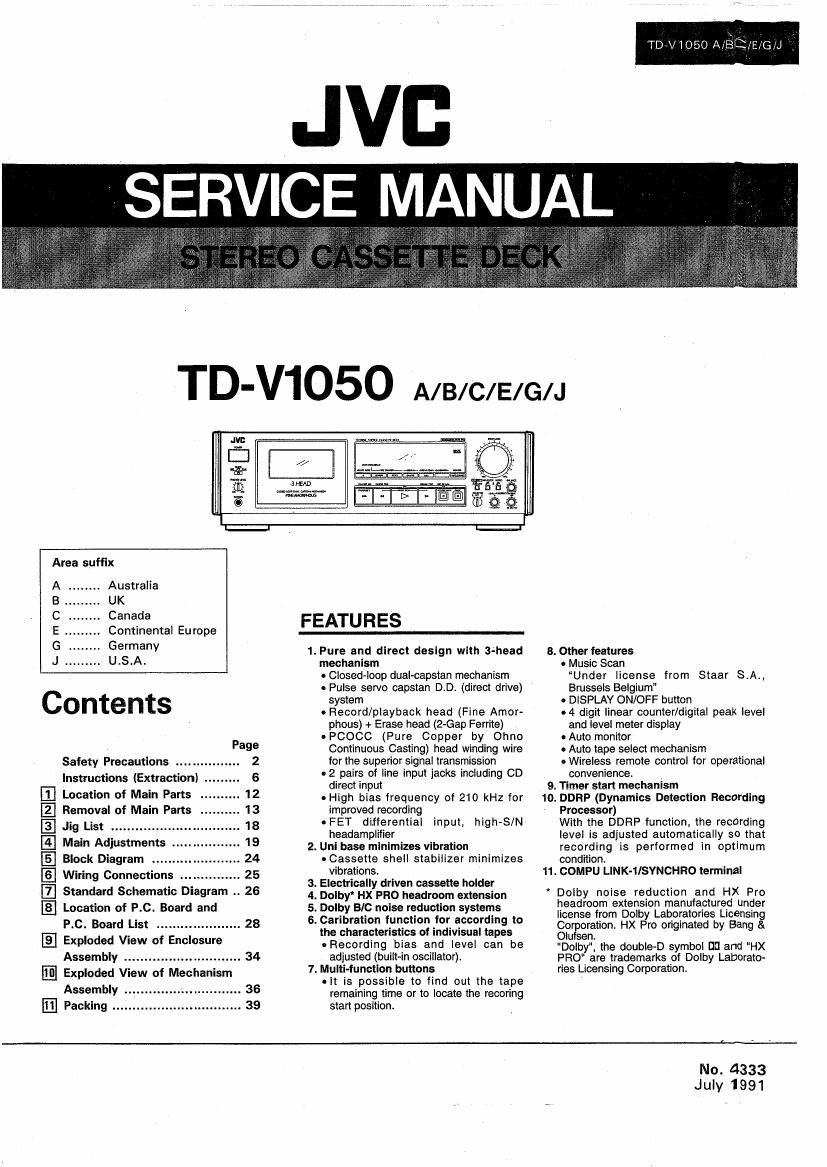
Jvc TDV 1050 Service Manual
This is the 40 pages manual for Jvc TDV 1050 Service Manual.
Read or download the pdf for free. If you want to contribute, please upload pdfs to audioservicemanuals.wetransfer.com.
Extracted text from Jvc TDV 1050 Service Manual (Ocr-read)
Page 1
l
Jill:
is a
Elli»- am
75 new
I-l
Area suffix
. Australia
UK
. Canada
Continental Europe FEATURES
Germany 1.Pure and direct design with 3-head
U.S.A. mechanism
0 Closed-loop dual-capstan mechanism
. Pulse servo capstan DiDi (direct drive)
Contents We
. Record/playback head (Fine Amor-
phous) + Erase head (2-Gap Ferrite)
. PCOCC (Pure Copper by Ohno
Page Continuous Casting) head winding wire
Safety Precautions ................ 2 for the superior signal transmission
Instructions (Extraction) .. 6 . 2 pairs of line input jacks including CD
Location of Main Parts . 12
Removal of Main Parts . 13
.. 18
Main Adjustments ..
Block Diagram .. 24
Wiring Connections 25
Standard Schematic Diagram .. 26
Location of P.C. Board and
El
El
E) Jig List ......................
El
El
El
P.C. Board List ..................... 28
E Exploded View of Enclosure
Assembly ...... ....... 34
Exploded View of Mechanism
Assembly .
E Packing
36
direct input
- High bias frequency of 210 kHz for
improved recording
- FET differential high-SIN
headamplifier
2. Unl base minimizes vibration
~Cassette shell stabilizer minimizes
vibrations
3. Electrically driven cassette holder
4. Dolby' HX PRO headroom extension
5. Dolby BIC noise reduction systems
6. Caribration function for according to
the characteristics of indivisual tapes
- Recording bias and level can be
adjusted (built-in oscillator).
7. Multi-function buttons
0 it is possible to find out the tape
remaining time or to locate the recoring
start position.
input,
TDVV 1050 A.JS1,EHG¢J
8. Other features
- Music Scan
Under license from Staar 5A.,
Brussels Belgium"
0 DISPLAY ON/OFF button
.4 digit linear counter/digital peak level
and level meter display
- Auto monitor
0 Auto tape select mechanism
owireless remote control for operational
convenience.
9. Timer start mechanism
10. DDRP (Dynamics Detection Recording
Processor)
With the DDRP function, the recording
level is adjusted automatically so that
recording is performed in optimum
condition.
11. COMPU LlNK-ilSYNCHRO terminal
' Dolby noise reduction and HX Pro
headroom extension manufactured under
license from Dolby Laboratories Licensing
Corggration. HX Pro originated by Bang &
Olu n.
"Dolby", the double-D symbol DD and HX
PRO" are trademarks of Dolby Laborato-
ries Licensing Corporation.
No. 4333
July 1991
Page 2
TD-V1050 A/B/C/E/G/J
2
e Safety Precautions
1. The design of this product contains special hardware and many circuits and components specially for safety
purposes. For continued protection, no changes should be made to the original design unless authorized in writing
by the manufacturer. Replacement parts must be identical to those used in the original circuits. Service should
be performed by qualified personnel only.
2. Alterations of the design or circuitry of the product should not be made: Any design alterations of the product
should not be made. Any design alterations or additions will void the manufacturer's warranty and will further -
relieve the manufacturer or responsibility for personal injury or property damage resulting therefrom.
3. Many electrical and mechanical parts in the product have special safety-related characteristics. These
characteristics are often not evident from visual inspection nor can the protection afforded by them necessarily
be obtained by using replacement components rated for higher voltage, wattage, etc. Replacement parts which
have these special safety characteristics are identified in the Parts List of Service Manual. Electrical components
having such features are identified by (A) on the schematic diagram and Parts List in Service Manual. The use
of a substitute replacement which does not have the same safety characteristics as the recommended replace-
ment part shown in the Parts List in Service Manual may create shock, fire, or other hazards.
4. The leads in the products are routed and dressed with ties, clamps, tubings, barriers and the like to be separated
from live parts, high temperature parts. moving parts and/or sharp edges for the prevention of electric shock
and fire hazard.
When service is required. the 'original lead routing and dress should be observed, and it should be confirmed
that they have been returned to normal, after re-assembling.
5. Leakage current check (Electrical shock hazard testing)
After re-assembling the product, always perform an isolation check on the exposed metal parts of the product
(antenna terminals, knobs, metal cabinet, screw heads, headphone jack, control shafts, etc.) to be sure the pro-
duct is safe to operate without danger of electrical shock.
Do not use a line isolation transformer during this check.
' Plug the AC line cord directly into the AC outlet. Using a Leakage Current Tester, measure the leakage
current from each exposed metal part of the cabinet, particularly any exposed metal part having a return path
to the chassis, to a known good earth ground. Any leakage current must not exceed 0.5 mA AC (r.m.s.l.
- Alternate check method
Plug the AC line cord directly into the AC outlet. Use an AC voltmeter having 1,000 ohms per volt or more
sensitivity in the following manner. Connect a 1,500 (I 10 W resistor paralleled by a 0.15 uF AC-type capacitor
between an exposed metal part and a known good earth ground.
. . AC V TMETER
Measure the AC voltage across the resistor With the AC @ (Hat/£1000 ohms/volt
voltmeter. or more sensitivity.)
Move the resistor connection to each exposed metal 0 c
___.__l
part, particularly any exposed metal part having a return
path to the chassis, and measure the AC voltage across
the resistor. Now, reverse the plug in the AC outlet and Place this probe
repeat each measurement. Any voltage measured must w on each exposed
not exceed 0.75 V AC (r.m.s.). 1500 ii 10 W metal part.
This corresponds to 0.5 mA AC lr.m,s.).
0.15 ,rF Ac TYPE
u
Good earth ground
-Warning
. This equipment has been designed and manufactured to meet international safety standards.
. It is the legal responsibility of the repairer to ensure that these safety standards are mainteined.
. Repairs must be made in accordance with the relevant safety standards.
. It is essential that safety critical components are replaced by approved parts.
. If mains voltage selector is provided, check setting for local voltage.
(5de
SELECTING THE Ac When this deck is used in an area where the
supply voltage is different from the preset
SUPPLY VOLTAGE voltage, reset the voltage selector to the
(A/B/E/G version only) correct position. A/B/E/G Verslon
Slide the voltage selector with a screwdriver so
that the desired voltage marking is in the
window.
The CIJ version Is not provided with
voltage selector. °?""°= .
Disconnect supply cord before changing the
voltage.
(No. 4333)
Page 14
D-V1050 A/B/C/E/G/J
I Cassette Door Cover (Lid)
1. Turn the power ON and press the eject button to open
the cassette door.
Pull the cover up to remove.
Assembly Parts
I When removing as the front panel assembly
(with mechanism)
1. Remove the top cover of the external parts. Remove the
front plate to prevent scratching.
2. Remove the cassette cover.
3. Pullout the input level knob. Pull the shaft knob section
upward to set it in the free position (see Figure 2-2).
4. Remove the four screws (59 retaining the PC board shield
case (see Figure 2-2).
5. Remove the wire from the main PC board (see Figure
2-2).
a) Remove CN804 of the Dolby switch/calibration
volume.
b) Remove the wires CN802, CN801 for record/playback
and erasing heads.
c) Remove CN704 going to the FL PC board.
d) Remove CN703, CN.713, CN702 and CN712 going .A_
to the leaf switch PC board. //
l
\.
9) Remove CNBOE and CN815 going to the headphone \ H \.
PC board. \Ké-x . l
6. Remove the cam switch wire lFW701l from the .1 Q. EEELSWWCI" 0
1. \ \Q card Remove the back
\\\\|iglt soldering.
Fig. 2-3
/
mechanism PC board connector.
7. Remove the screw © retaining the headphone PC board- @\ef/
grounding wire.
8. Remove the two screws ® retaining the mechanism
assembly on the chassis _
9. Remove the two screws retaining the front panel and
chassis on the bottom plate.
I PC board assembly inside front panel
lsee Figures 2-4 and 2-5). Fig. 2-4
1. Remove the front panel assembly.
0 Volume PC board assembly.
1. Pull out the volume knob.
2. Remove the three screws retaining the volume PC
board.
Timer PC
11 I1 6?
0 FL PC board assembly @-
. Remove the volume PC board. Fl/jfik O O [_/l
@
._\
. 49
2. Remove the mechanism assembly (removing the back EL@
. r
light soldering © ). - A- J Headphone
3. Remove the nine screws @ retaining the FL PC board. Volume = _g§-E£-T' j _ volume aSSembly
12
Headphone PC
0 Headphone PC board assembly board assembly
1. Remove the screw (hexagonal) retaining the headphone Fig. 2.5
jack.
14 (No. 4333)
Page 23
TD-V1OSO A/ElC/E/G/J
item Adjustment Method Alt-1:55;?) 3: Standard Value Remarks
9 Adjustment 1) While applying 1 kHZ signal, ad- VR805 Output 1) Whenever the output is by
and just the input on the monitor ON at - 34 dB +1 dB greater than the
confirma- (SOURCE) so that the line out- OFF at -36 dB specified input, 1. 2. 3...
tion of level put level becomes -34 st. will successively be in-
indicator Adjust VR805 so that (-30 dicated.
dB" of the FL level indicator is 2) When the output is less than
turned .on and both or one of the specified input, the max-
the indicators are turned on at imum value will be held for
-36 dBS- about 2 sec.
2) Indicator Line output level 3) €35 the [CALL] button to
O _4 st+1 dB indicate [pVEH 12 dB] for 5
+8 +2 stEZ dB see. by flickering.
-10 -14stiZdB
-30 -34 sti3 dB
10 Recording] 1) Record a 1 kHz signal so that Normal tape: Check after adjusting the bias
playback the LINE OUT output is -2 st 2% or less current and recording level.
distortion and the level indicator is +6 Chrome tape:
check dVB. 3% or less
2) Use a distortion gauge to check Metal tape:
it the output is the standard 2% or less
value during playback.
11 Recording] 1) Record 1 kHz, 0 dB input and Normal:
playback then remove the input and 38 dB or more
S/N ratio record without a signal. Chrome:
check 2) Playback this recording and 42 dB or more
measure the difference between Metal:
the 0 dB recording and no~signal 42 dB or more
recording. The standard values
must be satisfied.
12 Erase ratio 1) Apply a 1 kHz signal from LINE IN 55 dB or more Connect a B.P.F (band pass
check and adjust the lNPUT LEVEL knob filter) between the deck and
so that the input level is -8 st.
2) Increase the signal level to 20 dB
and record.
3) Rewind and erase the recorded
section of the tape.
4) Measure the output ratio between
the signal and no-signal sections of
the tape with an electronic
voltmeter.
the electronic voltmeter.
1 kHz 0 VU _, Deck record/
+ 20 dB input erase ll
(1 kHz)
,_ Band pass Electronic
filter (B.P.F.) voltmeter
(No. 4333) 23