Jvc SPE 37 BKE Service Manual

This is the 6 pages manual for Jvc SPE 37 BKE Service Manual.
Read or download the pdf for free. If you want to contribute, please upload pdfs to audioservicemanuals.wetransfer.com.

Page: 1 / 6
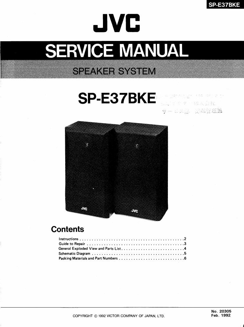
Jvc SPE 37 BKE Service Manual

Extracted text from Jvc SPE 37 BKE Service Manual (Ocr-read)


Page 1

SP-E37BKE

JVB
SERVICE MANUAL

SP-E37BKE

Contents
Instructions ........................................... 2
1 Guide to Repair ........................................ 3
General Exploded View and Parts List .......................... 4
Schematic Diagram ...................................... 5
Packing Materials and Part Numbers ........................... 6
No. 20305
COPYRIGHT © 1992 VICTOR COMPANY OF JAPAN, LTD. Feb. 1992

Page 2

SP E37BKE

Instructions

Amplifier connection CONNECTION

Verstfirkeranschlufl - Turn oft power to the whoie system belore connecting the speakers to
, . the ampirfier.

Raccordement é ' amplrtlcateur 0 The nominai Impedance of the SP-E37/SFE56 is 8 ohms. Connect them

Aansluiten op de versterker to an amplilier with the toad inpedance ol 8 ohms speaker.

ConeXIOn al ampliticador 0 The maximum power handling capacity of the SPVE37/SP-E56 is 50 watts.
, . . Excessive input will result in abnormal noise and possible damage. 70%
Collegamento dell amplificatore ol the maximum amplifier output is normally available when the volume
Anslutning till en forstfirkare control is set to its center position.
Forstarkertilslutnlng In cases where the signals described below are applied to the speak-
. . . .. .. ers. even it the signals are below the maximum allowable input, they may
Vahvrstlmen "Itanta cause an overioad and burn the Wiring of the speakers. Be sure to lower
the amplilier volume beforehand.
1) Noise during FM tuning
2) High level signals containing high frequency components produced
by a tape deck in the last forward mode
3) Click noise produced when turning power of other components on
and oil.

Right speaker Left speaker 4) agggoviesreggoduced when connecting or disconnecting cords wrth

21:22:: eLda root'sgrecher LEEESL':aUS$::he' 5) Click noise produced when the cartridge is replaced with the power on.

Recht r ids reker Linker Iuigs reker 6) Click noise produced when operating amplilier SWitches.

Altavoez duerecpho Aitavoz izquierdo 7) Continuous high frequency osciiatiori or high pitch eiectronically
oduced mu5ica| instrument sound.

Altopariarite destro Altoparlante srnislro pr . . i

Hoger hogtaiare Vanster hogtalare B) HOWIIHQ when usmg a microphones.

Hone hojttaler Venstre hoittaler Note:

Oikeanpuoleinen kaiutin Vasemmanpuoieinen kaiutiri - Although this system consists of low leakage magnetic flux type

_ speakers, the TV set may experience color fluctuations It the sys-
tem is lnsltalled too closely to it. If thls occurs, please move the

speaker: away train the set.

Amplifier output terminate
Ausgang des Verst'arkers
Bornes de sortie de l'amplrficateur
Uitgangsaansluitengen van de versterker
Terminales de salida de ampliiroador
Terminali di uscita deliampliiicatore
Utgéngar pa lorstarkaren
Forstaerkerudgangsbosninger
Vahvistimen uiostuloiiittimet

SPEA KERS


vRIGHT 7 - LEFT+ :g-Efigl7FICATIONs
Type : 2 way acoustic suspeDSion type
(Low leakage magnetic ilux type for AN)
Speakers:
Woofer : 16 cm (6-1/4") cone x 1
Tweeter : 5 cm (2") cone x 1
Power handling capacity : 50 watts
White stripe impedance : 8 ohms
> \ WeiBer Strerfen Frequency range : 70 Hz - 20,000 Hz
Hale blanche Sound pressure level : 89 dB/W'm
Witte slreep Dimensions (W x H x D) : 230 x 410 x 162 mm
Hilo blanoo (91/16" x 16-3/16" x 6-7/16")
Fascia bianca Weight : 31 kg (6.9 lbs) each
Vit rand
Hvrd sinbe

Valkoinen iuova

2( Not20305)