Jvc SPC 220 Service Manual

This is the 8 pages manual for Jvc SPC 220 Service Manual.
Read or download the pdf for free. If you want to contribute, please upload pdfs to audioservicemanuals.wetransfer.com.

Page: 1 / 8
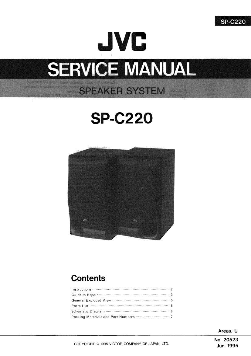
Jvc SPC 220 Service Manual

Extracted text from Jvc SPC 220 Service Manual (Ocr-read)


Page 1

SP~C226

JVC
SERVCE MANUAL

SP-C220

Contents

Instructions --------- 2
Guide to Repair 3
General Exploded View -- n 5
Parts List 5

Schematic Diagram

Packing Maieriais and Part Numbers --------------------------- 7

Areas. U

No. 20523

'05
COPYRIGHT 1995 VICTOR COMPANY OF JAPAN, LTD. Jun, 1995

Page 2

SP-CZZO

Instructions

Connection
Conex'ién
Ligacao
fit:
J-ev"
Black Press
Negro Presionar
P79) Pressione
g , a?
J:- LL21

2 (M20523)

CONNECTION

0 Connect the LEFT speaker terminals of the amplifier to
the LEFT terminals otthe speaker and RIGHT to RIGHT
using the attached speaker-cords as shown in the figure
making sure polarity is Contact: (+) to (+) and H to (-).
Connect the black speaker wires to the (-) terminals.
Turn off power.to the whole system before connecting
the speakers to the ampiifier.

The nominal impedance of the SP-C220 is 60hms.

Connect them to an amplifier with the load impedance of

6 ohms speaker.

The maximum power handling capacity of the SP-CZZO

is 4:0 wattsfixcessive input will result in abnormal noise

and possible damage. 70% of the maximum amplifier
output is normally available when the volume control is
set to its center position.

In cases where the signals described below are applied

to the speakers, even it the signals are below the

maximum allowable input, they may cause an overload
and burn the wiring of the speakers. Be sure to lower
the ampitliervolurne, beforehand.

1) Noise during FM tuning.

2) High level signals containing high frequency
components produced-by a tape deck in the fast
forward mode.

3)Click noise produced when turning power of other
components on and off.

4) Click noise produced when connecting or
disconnecting cords with the power on.

5)Click noise produced when the cartridge is replaced
with the power on,

6)Click noise produced when operating amplifier
switches.

7) Continuous high frequency oscillation or high pitch
electronically produced musical instrument sound

8) Howling when using a microphones.

o

o

SPECIFICATIONS

Type: : 3-way bass-reflex type

Speakers:
Woofer : 13.5 cm (5-3/8") cone x 1
Midrange ' 5 cm (2") cone X 1
Tweeter 2 cm (13 /16") dome x 1

Power Handling Capacity:

Impedance

Frequency Flange
Sound Pressure Level
Dimensions (W x H x 0)

Mass
Accessories

40 watts

6 ohms

58Hz - 20,000Hz

90dB/w ' m

183 X 329 X 247mm
(7-1/4" X 13" X 9-3/4')

2.7kg (6.0Ibs) each
Speaker Cord ................... 2

Design and specifications subject to change without notice.

Page 4

# SP-czzo K

.Replacing the speaker terminal
The speaker terminal assembly on the back
panel has two notches. (See Fig.3.)
insert the tip of a screwdriver into each of the

notches alternately and lift the terminal off.
(See Fig. 4.)

Note:
After replacing the assembly, apply rubber
cement(Diabond #1600MA or equivalent)to the
speaker terminal from the inSIde.(See Fig. 5.)

lMounting Ornament Assembly
When mounting the ornament and Saran Board
Assembly.(Fig.6) Ornament is first mounting.
Saran Board Assembly IS second mounting.

Saran Board Assy

C @ Ornament

(. c: to press

Fig.6

4 (M20523)