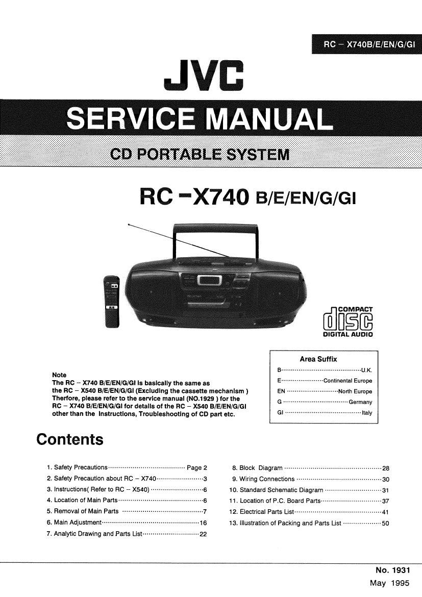
Jvc RCX 740 Service Manual
This is the 30 pages manual for Jvc RCX 740 Service Manual.
Read or download the pdf for free. If you want to contribute, please upload pdfs to audioservicemanuals.wetransfer.com.
Extracted text from Jvc RCX 740 Service Manual (Ocr-read)
Page 1
JVB
SERVICE MANUAL
RC - X74OB /EN/G/Gi
RC -X740 B/E/EN/G/Gl
riflfimg'fi
DIGITAL AUDIO
Area Suffix
Note
The RC - x740 B/E/EN/G/Gl ls basically the same as 5"
the RC - x540 B/E/ENIG/Gl (Excluding the cassette mechanism ) EN --------------------------- North Europe
Thertore. please refer to the service manual (No.1929 ) for the G Germany
Rc - X740 B/E/EN/G/GI for details of the RC - X540 BlE/EN/G/GI
other than the Instructions. Troubleshootlng of CD part etc. 3' " """ "my
1, Safety Precautions ...................................... Page 2 8. Block Diagram ............................
2. Safety Precaution about RC - X740 ---------------------- a 9. Wiring Connections ------------------------------------------ 30
3. lnstructions( Refer to RC - X540) -------------------------- 6 10. Standard Schematic Diagram ---------------------------- 31
4. Location of Main Parts ~~~~~~~~~~~~~~~~~~~~ ---6 11. Location of RC. Board Parts ------------------------------ 37
5. Removal of Main Parts -7 12. Electrical Parts List ----------------------------------------- 41
6. Main Adjustment --------------------------------- ~16 13. illustration of Packing and Parts List
7. Analytic Drawing and Parts List ---------------------------- 22
No. 1931
May 1995
Page 2
RC - X740 B/E/EN/G/Gl
__..t
I Cassette / Recorder Deck Sections
Item Conditions Adjustment & Confirmation Methods Stand. values Adjust
Head azimuth . Test tape * Adjust the head azimuth screw only when the head Within 2dB of Head
adjustment : VTT703L(10kHz) is replaced. the peak level azimth
(A. B mechanism) - Output terminal ®Playback test tape VTT703L( 10kHz) . Minimum adjusting
for measurement ®Adjust the head azimuth so that the phase phase screw
: Headphone difference is minimum (Within 2dB of the peak difference
- Input terminal for level of play output.) After adjustment apply the
measurement screw locking adhesive to the head azimuth screw
: CN301 more than a half arund the screw head.
Tape speed - Tast tape (DWhen playing test tape VTT712 (3kHz). - Tape speed VRA61
adjustment and : VTT712 (3kHz) ®Adjust VRA61 so that the frequency counter : 2990Hz
wow &Flutter - Output terminal reading is 2990Hz ~3010Hz . ~3010Hz
checking for measurement ® Wow &Flutter should be less than 0.38%(JIS
(A, B mechanism) : Headphone UNWTD) Wow &Flutter
: Less than
0.38%(JIS
UNWTD)
Play back output - Tast tape @When Playback the test tape VTT724 (1kHz) . - 26dB :
level checking : VTT724 (1 kHz) the output level at headphone is - 26dB : 3dB 3dB
(A, B mechanism) -Output terminal at 1kHz.
for measurement @Deviation L and R 2 less than adB
: Headphone
Playback o Tast tape When playback the test tape VTT736, response 63Hz and
frequency : VTT736 should be - 3dB : 4dB at SSH: and 1kHz, +1dB : 1kHz
response -Output terminal 4dB at 10kHz and 1kHz with respect to 1kHz. : .. 3GB :
checking for measurement 4dB
(A, B mechanism) : Headphone 10kHz and
1kHz
+1 dB : 4dB
Record / - Reference @Record and playback the 1kHz reference
playback frequency frequency and 10kHz signal and check at
frequency : 1kHz, 10kHz treminal CN301.
response (Ref. - 20dB) @Adjust the VFtA41 so that record and playback VRA41
adjustment - Test tape : frequency response with 1kHz and 10kHz at + 1dB i 1dB
(A mechanism) A0224 CN301 is +1dB : 1dB
- Output terminal ®Comfirm that the frequency counter reading is 95.5kHz :
for measurement 95.5kHz i 3kHz. If the reading is out of this 3kHz LA341
:CN301
range, adjust LA341.
18 (No.1931)
Page 10
RC7X
RC - X740 B/E/EN/G/Gl
I Enclosure Assembly Part: Block Nam-5]
(No. 1931) 24