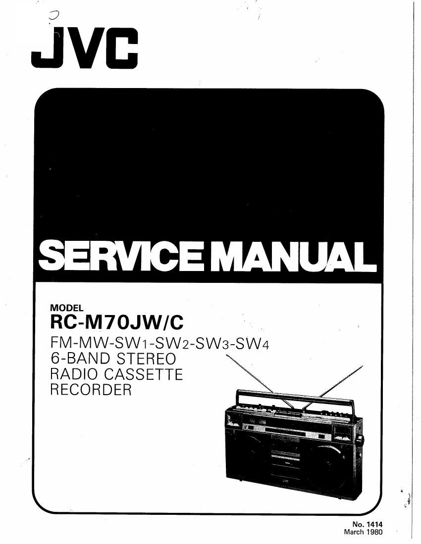
Jvc RCM 70 JWC Service Manual
This is the 38 pages manual for Jvc RCM 70 JWC Service Manual.
Read or download the pdf for free. If you want to contribute, please upload pdfs to audioservicemanuals.wetransfer.com.
Extracted text from Jvc RCM 70 JWC Service Manual (Ocr-read)
Page 2
' 4
RC-M70JW/C
Contents
Page
Specifications .............................. 2
Operating Principle of MULTI MUSIC SCANNER
Automatic program selection facility) ............ 3
Block Diagram of MMS ........................ 3
Main Parts Location .......................... 4
Removal of Parts ............................ 5
Removal of Parts of Cassette Mechanism ............ 6
Specifications of Cassette Mechanism .............. 6
Adjustment of Cassette Mechanism ................ 7
Adjustment of Cassette Recorder Amplifier .......... 7
Exploded View of Cassette Mechanism ............. 8
Parts List of Cassette Mechanism ................. 9
Tuner Alignment ............................ 10
How to Engage Dial Cord ..................... 12
Block Diagrams ............................ 12
Schematic Diagram of RC-M70JW/C (Tuner) ........ 13
Schematic Diagram of RC-M70JW/C (MMS Control) . . .14
Specifications
DIMENSIONS: 55.4 cm(W) x 30.3 cm(H) x 15.1 cm(D)
TUNER SECTION
Frequency Ranges : FM 88 - 108 MHz
MW 540 - 1600 kHz
SW1 1.6 - 4.3 MHz
SW2 4.3- 11 MHz
SW3 11 e 18.5 MHz
SW4 1825 - 26 MHz
RECORDER SECTION
Tape Speed
Track System
Recording System
Erasing System
Fast Forward Time
Rewinding Time
Wow & Flutter
AMPLIFIER SECTION
Speakers
Power 0 utput
No. 1414
: 4.8 cm/s (1-7/8 ips)
: 4-track 2-channel stereo
: AC Bias
: AC Erasing
: Within 110 sec. (0-60 cassette)
: Within 110 secs (C-60 cassette)
: 0.065% (WRMS)
: 16 cm (6-1/2") x 2, 5 cm (2") x 2
I 7.0 W per channel, min. RMS
(100 Hz~15 kHz, 8 ohms, 10 %
THD)
Max. 30W (15W+ 15W)
Page
Schematic Diagram of RC-M70JW (Amplifier) ....... 15
Tuner, Volume and
Switch Circuit Board Assemblies .............. 16
Circuit Board Assemblies (Power Supply, Jack,
Auto-stop, MMS Switch, MMS LED, Metal LED
and Stereo LED, Motor) .................... 20
Amplifier and Muting Circuit Board Assemblies ....... 24
Wiring Connection .......................... 28
Exploded Views of Front Cabinet ................ 29
Exploded Views of Rear Cabinet ................ 32
Exploded Views of Main Chassis Assy ............. 33
Exploded Views of Tuner Chassis Ass'y and
Power Supply Assy ....................... 36
Exploded Views of Amplifier Chassis Ass'y ......... 37
Final Packing Assy ................... Back cover
Accessories ......................... Back cover
WEIGHT: Approx. 9.0 kg (with batteries)
Input Jacks : MIC x 2 (low impedance)
Line In x 2 (100 mV, 50 kfl)
Phono x 2 (3 mV, 50 kt?)
Output Jacks 2 Ext. Speaker x 2 (8 Q)
Headphones (8 - 32 9)
Line Out x 2 (250 mV,10 k0)
POWER CONSUMPTION: 40 W (JW),47 W (C)
SEMICONDUCTORS
ICs : 12 (includes microphones)
Transistors : 49 (includes motor governor)
Diodes : 64
POWER SOURCE
DC : 15 V, 10 "D, R20 cells or
equivalent
AC : 240/220/120 V, 50/60 Hz (JW)
120 V, 60 Hz (C)
Design and specifications subject to change without notice,