Jvc RCBZ 5 BU Service Manual

This is the 99 pages manual for Jvc RCBZ 5 BU Service Manual.
Read or download the pdf for free. If you want to contribute, please upload pdfs to audioservicemanuals.wetransfer.com.

Page: 1 / 99
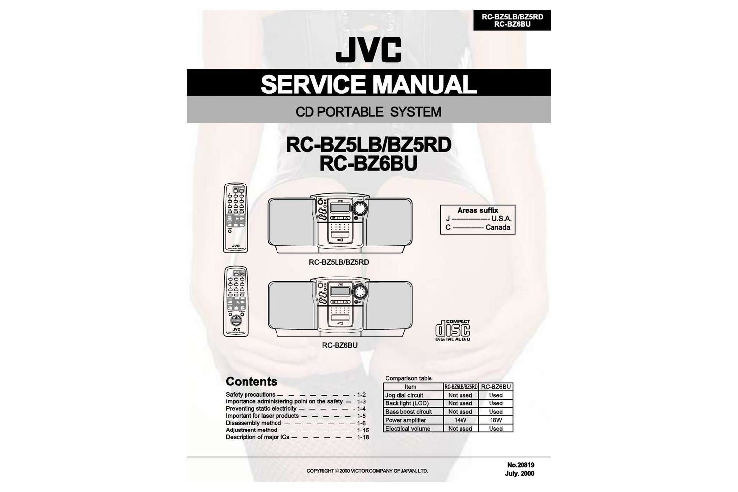
Jvc RCBZ 5 BU Service Manual

Extracted text from Jvc RCBZ 5 BU Service Manual (Ocr-read)


Page 2

RC-BZSLB/BZ5RD
RC-BZGBU

-Safety precautions

1-2

1.This design of this product contains special hardware and many circuits and components specially
for safety purposes. For continued protection. no changes should be made to the original design
unless authorized in writing by the manufacturer. Replacement parts must be identical to those
used in the original circuits. Services should be performed by qualified personnel only.

2.Alterations of the design or circuitry of the product should not be made. Any design alterations of
the product should not be made. Any design alterations or additions will void the manufacturers
warranty and will further relieve the manufacture of responsibility for personal injury or property
damage resulting therefrom.

3. Many electrical and mechanical parts in the products have special safety-related characteristics.
These characteristics are often not evident from visual inspection nor can the protection afforded
by them necessarily be obtained by using replacement components rated for higher voltage,
wattage, etc. Replacement parts which have these special safety characteristics are identified in
the Parts List of Service Manual. Electrical components having such features are identified by
shading on the schematics and by (A;) on the Parts List in the Service Manual. The use of a
substitute replacement which does not have the same safety characteristics as the recommended
replacement parts shown in the Parts List of Service Manual may create shock, fire, or other
hazards.

4.The leads in the products are routed and dressed with ties, clamps, tubings, barriers and the
like to be separated from live parts, high temperature parts, moving parts and/or sharp edges
for the prevention of electric shock and fire hazard. When service is required, the original lead
routing and dress should be observed, and it should be confirmed that they have been returned
to normal, after re-assembling.

5. Leakage current check (Electrical shock hazard testing)
After re-assembling the product, always perform an isolation check on the exposed metal parts
of the product (antenna terminals, knobs. metal cabinet, screw heads, headphone jack, control
shafts, etc.) to be sure the product is safe to operate without danger of electrical shock.

Do not use a line isolation transformer during this check.

0 Plug the AC line cord directly into the AC outlet. Using a "Leakage Current Tester", measure
the leakage current from each exposed metal parts of the cabinet, particularly any exposed
metal part having a return path to the chassis. to a known good earth ground. Any leakage
current must not exceed 0.5mA AC (r.m.s.)

.Alternate check method
Plug the AC line cord directly into the AC outlet. Use an AC voltmeter having, 1,000 ohms
per volt or more sensitivity in the following manner. Connect a 1,5009 10W resistor paralleled by
a 0.1511 F AC-type capacitor between an exposed

metal part and a known good earth ground. a girl/ISSAAIEJER
Measure the AC voltage across the resistor with the ohms/yous,

AC voltmeter. or more sensitivity)
Move the resistor connection to each exposed metal ° c

part, particularly any exposed metal part having a (115): ACTYPE

return path to the chassis, and measure the AC _| Place this
voltage across the resistor. Now reverse the plug in |_ probe on

the AC outlet and repeat each measurement voltage W) V each exposed

measured any must not exceed 0.75 V AC (r.m.s.). 15009 10W metal part.

This corresponds to 0.5 mA AC (r.m.s.).
Good earth ground

A CAUTION Buns formed during molding may be left over on some parts of the chassis. Therefore,

pay attention to such burrs in the case of preforming repair of this system.

Page 12

RC-BZSLB/BZ5RD
RC-BZSBU

lRemoving the power transformer
assembly (See Fig.20)

- Prior to performing the following procedure, remove
the front cabinet assembly and the rear cabinet
assembly.

1. Disconnect the harnesses from connector CN306
and CN307 on the power board in the power
transformer assembly.

2. Remove the two screws H attaching the AC jack of
the power board and the two screws l attaching the
power transformer.

Remove the power transformer assembly toward the
front.

lRemoving the battery board
(See Fig.21 and 22)
- Prior to performing the following procedure, remove

the front cabinet assembly and the rear cabinet
assembly.

1. Disconnect the battery terminal wire from connector
CN307 on the power board.

2. Remove the battery board on the back of the rear

1-12

cabinet.

Power transformer assembly

Power board
CN307

Release the homese

Fig.21

Power board
CN307

Battery board

I

Fig.22

[i

nu murmur

Page 44

Teclas numén'cas

H

TUNER BAND

Podré escuchar emisoras de FM y de AM. Las emisoras se pueden
sintonizar manualmenve, automaficamenve o desde las presintonlas
almacenadas en la memoria.

Radio mediante un sélo bot6n (sdlo

corriente alterna (GAD

Presione S610 e1 botén TUNER BAND para que el equipo se ancien-

da y se escuche la emisora que tenia seleccionada cuando apagé el

equipo.

I También puede cambiar desde cualquier otra fuente de audio a
la radio con sélo pulsar e1 botén TUNER BAND.

Sintonizacién de una emisora

1. Presione el bot6n TUNER BAND.
En la pantalla apareceran la banda y la fiecnencia sintonizadas
en I'lltirno lugar.
Cada vez que presione e1 hotén, la banda Gambia del siguiente
modo:

I- FMAuto -> FM MONO -> AM -> -|

z. Seleccione una emisora eon uno de Ios
métodos siguientes.

I Sintonizacidn manual
Presione e1 botén H4 0 e1 botén >>l varias veces para pasar de
frecuencia a fi'ecuencia hasta encontrar 1a emisora deseada.

nan

.« W I44 >>I
m o r
M $1 93
O

I Sintonizacién automatica
Si pulsa y mantiene pulsado el b01611 H4 0 >>l durante un se-
gundo 0 axis, la frecuencia cambiaré, hacia abajo o hania arriba,
autométicamenw hasla encoutrar una emisora.
O
I Sintonizacldn en el equipo de presintonias (sélo
cuando se hayan presintonizado emisoras)
Presione el botén l PRESET para seleccionar la emisora sin-
tom'zada con anteriotidad. Cuando haya seleccionado él nfimero
de presintonia, la banda y la frecuencia correspondientes apare-
ceran en la pamalla.
Ejemplo: Presione el botén l PRESET hasta que aparezca en
pautalla 1a presintonia n° 12 P- 12.

I'l l "I I" Ivl II'
I I |_ " I ll

0

Use del sintonizador

Mando giratorio JOG

.. \
mgw '
TUNER BAND PRESET

Presentacién de banda. presenlacién de lreouencia. canal de prefijado

l-I'

|_ :U: H ll. . Relojanalbgico
smea- JIM?
MONO

(Mostrar a1 usar e1 sintonjzador)

I Sintonice con el mando a dislancia las presinlonias
(sélo cuando se hayan presintonizado emisoras).
Seleccione 1a emisora introduciendo e1 mimero de presintonia
en las teclas numericas.

- Ejemplo: Para cl canal 5, presione el 5. Para :1 canal 15
presione +10 y luego e1 5.
Se visualizan la banda y la frecuencia.

3. Giro Ia antena para mejorar Ia recepcién.
- Alargue y gire 1a antena telescépica para las emisoras FM.

- Para sintonizar emisoras AM basta con utilizar el equipo.

Para AM

Presintonia de emisoras

Se pueden presintonizar hasta 15 emisoras de FM y hasta 15 emiso-
tas de AM con el mando a distancia

Presintonizacién automatica (desde
el equipo)
En cada banda puede prefijar autométicamente 15 emisoras FM y
15 AM. Los mimeros presintonizados se distribuiréu a medida que

se encuenlren las emisoras empezando por la fiecuencia en 1150 y
buscando hacia arriba.

1.Seleccione una banda (AM o Fllll) pmio-
nando el botén TUNER BAND.

2. Presione ol boron l PRESET durante mas
do dos segundos.
3. Repita Ios pasos 1 y 2 para la otra banda.

I Si desea realizar alglm cambio en las emisoras presintonizadas
automAficamenlz, siga e1 procedimiento de ptesintonizacién
manual.

GUIDADO: si desenchula el equipo 0 se va Ia cor-
rienle, Ias presinlonias se borraran transcurridos
aproximadamenle cinco minutes. Si sucediera,
neeesitara volver a programar Ias emisoras.
Presintonizacion manual (con el
mando a distancia)

w Tecla(s) numérica(s) (pulsar durame 2

[iii f In * W... 11

Page 54

Raccordement du cordon d'alimentation secteur

Introduisez fermement 1e cordon dalimentation secteur foumi dans la borne secteur située au dos de 0
lappareil.

Le cordon d'alimentation secteur fourni avec cet appareil ne peut étre branché que dans un seul sens
afin d'evier tout risque de choc électrique. Se référer é lillustration pour le raccorder conectement.

_
4- 8-] )m
ATTENTION :
- N'UTILISEZ PAS D'AUTRE GORDON D'ALIMENTATION QUE LE COR-
DON JVC FOURNI AVEC LE PRESENT APPAREIL POUR EVITER TOUT MAUVAIS FONCTIONNEMENT OU
DES DEGATS MATERIELS.
- DEBRANGHEZ TOUJOURS LE GORDON D'ALIMENTATION DE LA PRISE SECTEUR LORSQUE VOUS
PARTEZ OU QUE VOUS NE COMPTEZ PAS UTILISER L'APPAREIL PENDANT UN CERTAIN TEMPS.

Vous pouvez a present brancher le cordon d'alimentation secqu dans la prise secteur e! I'appareil est
pro! 3 recovoir vos commandos!

GOMPU PLAY (alimentation secteur uniquement)

La fonction COMPU PLAY de IV C permet de commander les fonctions 1% plus utilisées de la chaine é laide dune seule touche.

Les operations a une seule touche permettent d'écouter un CD ou une cassette, dallumer 1a radio, etc. en appuyant simplement sur la touche
de lecture conespondant é cette fonction. La pression dune seule touche met lappareil sous tension pour vous et démarre la fonction demandée.
Si 1a chaine nest pas préte (par exemple, pas de CD dans le tiroir), elle se met malgre tout en marche pour vous permettre dintroduire un CD.
Le fonctionnement des operations it une seule touche est expliqué pour chaque cas dans le chapitre qni traite de la fonction conespondante.
Les touches COMPU PLAY sont :

Sur I'appareil Sur la Iélécornlnande

Touche CD >III Touche CD VIII
Touche TUNER BAND Touche TUNER BAND
Touche PLAY (TAPE)

0 érations communes

Témoin POWER 7
POWER POWER
Témoin STANDBY
SOUND Commands de VOLUME

AHB PRO

SOUND AHB PRO .. o . .

o n
i-VOLUME +, _ 5
PHONES

I Si vous écoutiez 1e tuner, 1e demier émetteur sélectionne revient
automatiquement.
Remarque: Lots du foncfionnement sur piles, la touche POWER
de la telecommande ne fonctionne pas.

Mettez I'appareil hors attente

Mettez sous et hors attente

Misc sous tension de I'appareil -
Appuyez sur la touche POWER.

POWER .

pomiéa 0 3/? Appuyez a nouveau sur la touche POWER.
mg Lors du fonctionnement sur secteur:
.5 POWER
PoviEii gm
Le témoin POWER ON (vert) sallume et laffichage séclaire. 011 Eugwi

Lappai'eil se met en marche, prét é continuer dans le mode of: i1 56

trouvait lors de sa demiére misc hots tension.

I Ainsi, si vous écoutiez un CD en demier lieu, vous étes prét
pour écouter 2: nouveau un CD, mais vous pouvez changer pour
toute autre source si vous le souhaitez.

/\

Le te'moin STANDBY sallume et les affichages seffacent.

I Lorsque lappareil est en mode Standby, i1 continue 3 utilise:
une faible quantité d'énergie (2,8 W) pour laflichage.

I Pour éteindre completement lappareil, débranchez 1e cordon
dalimentation de la pfise secteur.

3