Jvc QLY 66 F Service Manual

This is the 28 pages manual for Jvc QLY 66 F Service Manual.
Read or download the pdf for free. If you want to contribute, please upload pdfs to audioservicemanuals.wetransfer.com.

Page: 1 / 28
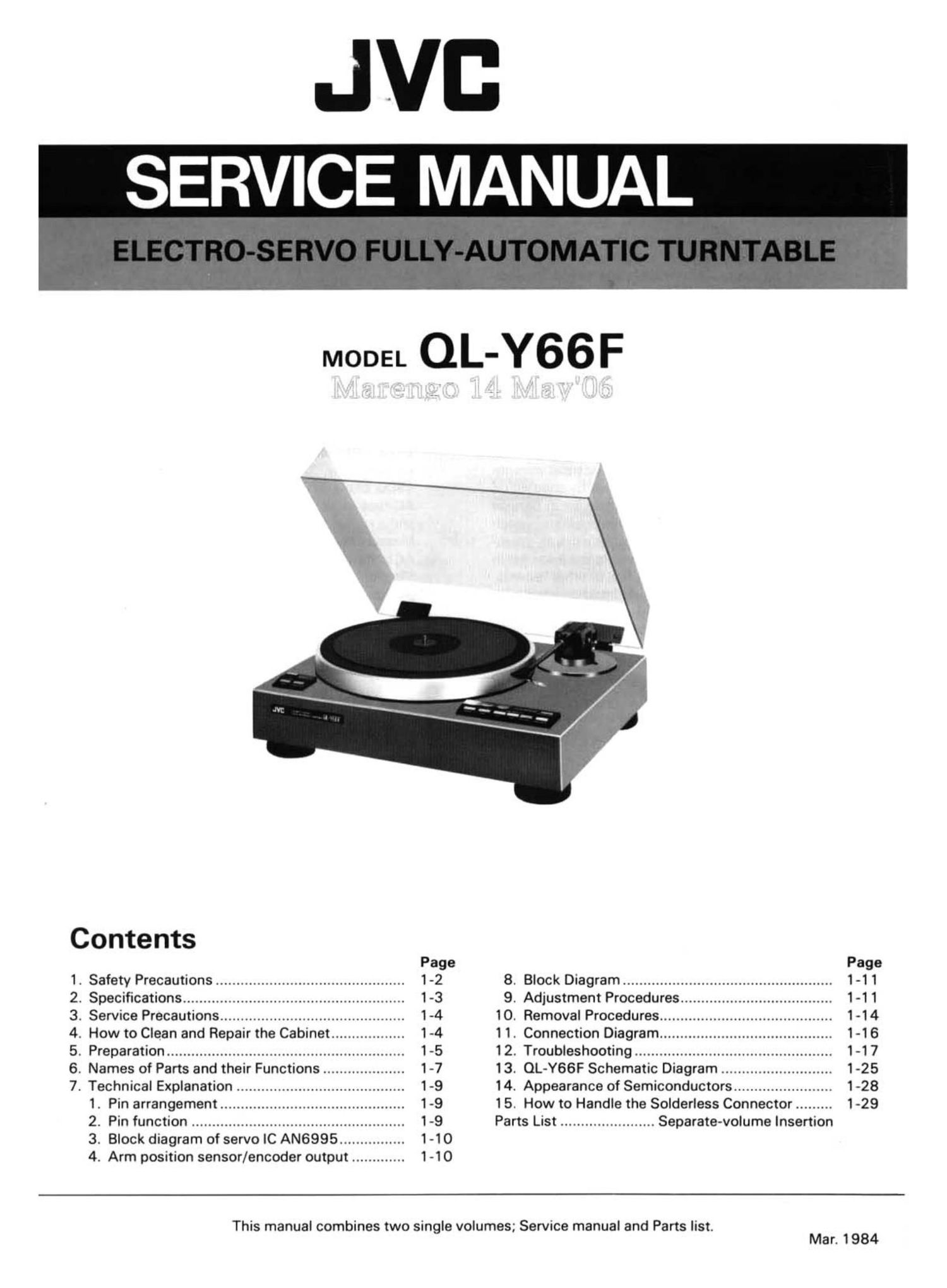
Jvc QLY 66 F Service Manual

Extracted text from Jvc QLY 66 F Service Manual (Ocr-read)


Page 1

JVI:
SERVICE MANUAL

MODEL QL-Y66F

Contents
Page Page

1. Safety Precautions .............................................. 1-2 8. Block Diagram ................................................... 1-1 1
2. Specifications ...................................................... 1-3 9. Adjustment Procedures ..................................... 1-1 1
3. Service Precautions ............................................. 1-4 10. Removal Procedures .......................................... 1 -14
4. How to Clean and Repair the Cabinet .................. 1-4 1 1. Connection Diagram .......................................... 1-16
5. Preparation .......................................................... 1-5 12. Troubleshooting ................................................ 1-17
6. Names of Parts and their Functions .................... 1-7 13. OL-Y66F Schematic Diagram ........................... 1-25
7. Technical Explanation ......................................... 1-9 14. Appearance of Semiconductors ........................ 1-28

1. Pin arrangement ............................................. 1-9 1 5. How to Handle the Solderless Connector ......... 1-29

2. Pin function .................................................... 1-9 Parts List ....................... Separate-volume Insertion

3. Block diagram of servo IC AN6995 ................ 1 -10

4. Arm position sensor/encoder output ............. 1 -1O

This manual combines two single volumes; Service manual and Parts list.
Mar. 1984

Page 2

1. Safety Precautions

1. The design of this product contains special hardware,

many circuits and components specially for safety pur-
poses.

For continued protection, no changes should be made
to the original design unless authorized in writing by
the manufacturer. Replacement parts must be identical
to those used in the original circuits. Service should be
performed by qualified personnel only.

. Alterations of the design or circuitry of the product
should not be made. Any design alterations or addi-
tions will void the manufacturer's warranty and will
further relieve the manufacturer of responsibility for
personal injury or property damage resulting therefrom.
. Many electrical and mechanical parts in the product
have special safety-related characteristics. These char-
acteristics are often not evident from visual inspection
nor can the protection afforded by them necessarily be
obtained by using replacement components rated for
higher voltage, wattage, etc. Replacement parts which
have these special safety characteristics are identified
in the parts list of Service manual. Electrical compo-
nents having such features are identified by shading on
the schematics and by ( A ) on the parts list in Service
manual. The use of a substitute replacement which
does not have the same safety characteristics as the re-
commended replacement part shown in the parts list in
Service manual may create shock, fire. or other hazards.
. The leads in the products are routed and dressed with
ties, clamps, tubings, barriers and/or the like to be sep-
arated from live parts, high temperature parts, moving
parts and/or sharp edges for the prevention of electric
shock and fire hazard.

When service is required, the original lead routing and
dress should be observed, and they should be con-
firmed to be returned to normal, after reassembling.

1-2 (No. 2767)

5. Leakage current check

(Safety for electrical shock hazard)

After reassembling the product. always perform an iso-

lation check on the exposed metal parts of the Products

(antenna terminals, knobs, metal cabinet. screw heads,

headphone jack. control shafts, etc.) to be sure the pro-

duct is safe to operate without danger of electrical
shock.

Do not use a line isolation transformer during this

check.

0 Plug the AC line cord directly into the AC outlet. Us-
ing a Leakage Current Tester", measure the leakage
current from each exposed metal part of the cabinet.
particularly any exposed metal part having a return
path to the chassis, to a known good earth ground.
Any leakage current must not exceed 0.5 mA AC
(r.m.s.).

0 Alternate check method.

Plug the AC line cord directly into the AC outlet. Use
an AC voltmeter having 1,000 ohms per volt or more
sensitivity in the following manner. Connect a
1500 ohms 10W resistor paralleled by a 0.15 uF
AC-type capacitor between an exposed metal part
and a known good earth ground.

Measure the AC voltage across the resistor with the
AC voltmeter.

Move the resistor connection to each exposed metal
part, particularly any exposed metal part having a re-
turn path to the chassis, and measure the AC voltage
across the resistor. Now, reverse the plug in the AC
outlet and repeat each measurement. Any voltage
measured must not exceed 0.75V AC (r.m.s.).

This corresponds to 0.5 mA AC (r.m.s.).

4+ AC VOLTMETER
V A N (HAVING IOOOQ/V,
OR MORE SENSITIVITY)

0.1 5yF AC-TYPE
-l I-

e m 3
1500.010W

PLACE THIS PROBE
> ON EACH EXPOSED
METAL PART

GOOD EARTH GROUND

Page 9

3. Block diagram of servo IC AN6996

Input amp ~\ Comparator 1 Comparator 2

rive amp source
W» 9 4 .7 K 7
Protection
circuit


---------------1

.-

56

I
I

I

I
I
----------------J

I
I
l
l
I
I

vs:
as"- e e e e e sin/591.6225.-.

-11.4V Output +11.4V

Fig. 14
Note:
1. PLAY refers to the arm which is on the record on play
Respective modes according to logic inputs or is at the rest position.
L ic in-ts V'- "TM ode " 2. DOWN refers to the arm which is lowering down.
09 p" . _ ii 3. UP refers to the arm which is to lift up or is lifting up.
A a ?"z°"°' Y'mFa' 4. LEFT and RIGHT refer to the arm which is moving left
direction direction or right.
0 0 PLAY PLAY J 5. STOP refers to the arm which stops at the UP position.
1 O l. DOWN
0 1 R UP
j- Note: Logic 0 = 0V ("L")
1 1 STOP ZERO BAL Logic 1 = +5V (H")

4. Arm position sensor/encoder output

This inputs the indicating signal of the current arm po- The respective tonearm addresses are as shown in the
sition to the microprocessor to detect the lead-in and table below. The table shows that. unless specific sig-
lead-out locations of the 30-cm or 17-cm record. As nals are input to the microprocessor from the encoder,
the tonearm moves horizontally, the output of the en- the tonearm does not operate normally.
coder changes, indicating the tonearm position (ad-
dress).
Encoder outputs
Tonearm position and operation
1 (Pin 30) 2 (Pin 31) 3 (Pin 32
On rest 0 O 0
Just released from rest 0 0 1 d 5
When lead in to 30-cm record 0 1 1 , , . .
On p, of 304:, record 0 1 O E 3, Note:The orderflof the items under 'Tonearm position and
_ =- operation corresponds to the sequence of the tone-
When lead into 17-cm record 1 1 0 s an movement
On play of 17-cm record 1 O 0 fl '
When lead out to 30~cm record 1 O 1
W2enleadoufl1lfliresord _ 1+ 1 L 1-

1-10 (No. 2767)

Page 10

8. Block Diagram

Tracking-Force
Control

Circuit

Detected Voltage Signal for . .
Vertical-Velocity © .._.. Vertical Dnvrng
Detecting Coil Servo Loo Vertical
p ' CC .1
@tric Current for 8&9 git-Janet Maximum UP
' - ' ' am in twin ' - -
g::::;'cl:|if'ectlon © 9 9..__ Circui? Posmon Detection g
C:: Disc Surface 8 Zero-Balance
Constant Electric Current for Detection g. Start/Stop
Tracking-Force :5
Damping a,
Control 9
,.
3.
Signal for O
Detected Voltage . . _ 0 U /D
Horizontal-Velocity© __... Horizontal Drivmg f." <9 >°""
. . ' C
Detecting Conl Servo Loop gonzo? 5' Size
Electric Currenlt3 for Electric D "9 Arm Rest Position Repeat
"Vln '
Horizontal-Direction © 4- ampin 9 Detection

Driving Coil x 2

6)

C:

Constant Electric Current
for Anti-Skating

Anti-Skating
Control

Direct Drive Motor

9. Adjustment Procedures

I Headshell Angle

If the headshell is not horizontal and the stylus tip is not
perpendicular to the record surface, loosen the lock
screws as shown in the illustration and move the head-
shell to adjust the stylus to be at right angles (90) with
the platter. Eye-measurement is sufficient.

Be sure to retighten the screws after the adjustment is
completed.

I Overhang adjustment
0 Straight-type arm pipe
Adjust the overhang so that the distance between
the headshell edge and the stylus tip is 47 mm as
shown in Fig. 17.

Stylus tip

Headshell

. . Speed
Motor Drivmg Select
Circuit .
Swrtch

Fig. 15

/

Fig. 1 6
S-shaped arm pipe
Adjust the overhang so that the distance between the
headshell edge and the stylus tip is 48 mm as shown in
Fig. 18. The ring washer in the parts box is to be used
as shown in Fig. 18 and should be fixed firmly.
Note: A difference of x 1 mm will not degrade the
performance.

Headshell

Stylus tip Ring washer

48 mm

Fig. 18

(No. 2767) 1-11

Page 13

10. Removal Procedures

' First detach the platter before disassembling work.

I Removal of bottom board

1. Remove the 9 screws mounting the bottom board.

2. Remove in the following manner to avoid damaging the
signal board. Hold the signal cord while raising the
front side of the unit, then pull out the bottom board to
wards the front side of the unit.

3. Remove two power cord clamper retaining screws.
(U.S.A. and Canada only)

Removal of motor

Remove the bottom board. (See item above.)

Remove the 2 screws mounting the motor board.
Disconnect the 2 ground wires.

Return the unit to its normal position.

Remove the 4 screws mounting the motor cover.
Remove the 3 hexagon socket headed cap screws and
2 oval flat-headed wood screws. Be careful not to lose
the washers.

7. Lift up the motor and disconnect the 5-P connector.

@WPPNT.

I Removal of vertical coil (Figs. 24 and 25)

1. Remove the 4 screws mounting the coil cover. (Use a
screwdriver for pin faced screws.)

2. Taking care not to cut any coil lead, remove the coil sol-
dering on the board.

3. Pull out the main weight.

4. Remove the 4 screws and nuts securing the coil clamp.

5. Lift up the coil clamp, and pull out the coil taking care
not to damage it.

Note: As the coil leads are thin and easy to cut, be careful

in handling them.

I Removal of tonearm section (Figs. 26 and 27)
1. Remove the bottom board. (Refer to Removal of bot-
tom board")

2. Remove the soldering of the 5 leads running to the sig-

nal board.

Disconnect the ground wire.

Disconnect the connectors (lo-P and 6-P) connected

to the horizontal coil board and the lamp house.

5. Remove the 3 special screws mounting the arm base.

6. Return the unit to its nomal position.

Note: When the arm pipe has been removed by loosening
its setscrew to protect the cartridge, etc. against
damage, the removal operation is easily performed.

PS"

I Removal of V.D. Generator (Figs. 25 and 27)

. Remove the bottom board.

. Remove the soldering of the 5 leads leading to the sig-
nal PC. board and that of the 6 leads leading to the hor-
izontal drive coil board.

3. Remove the coil cover.

4. Remove the 2 screws securing the V.D. generator.

(With a hex wrench of opposite side distance 1.5 mm)

Notes:

0 When mounting the V.D. generator, position the gener-
ator by turning the yoke so that the lead-in adjustment
screw is located at the center of the adjustment hole.

0 When inserting the generator in the bearing shaft, in-
sertion should be carried out with a slight pull of the
wire to protect the wire from being caught or cut.

N-l

1-14 (No. 2767)

Arm pipe
setscrew Coil cover

Coil clamp
securing screw

Motor .nounting
wood screw

Motor

Motor cover

Control panel (L)


Fig. 24

\ Coil clamp

Fig. 25

Motor mounting
hexagon screw

Control panel (R)

Fig. 26

Pin faced screws

Counterweight

V.D. generator
securing screw
(located deep
inside)

Lead-in
adjustment
hole