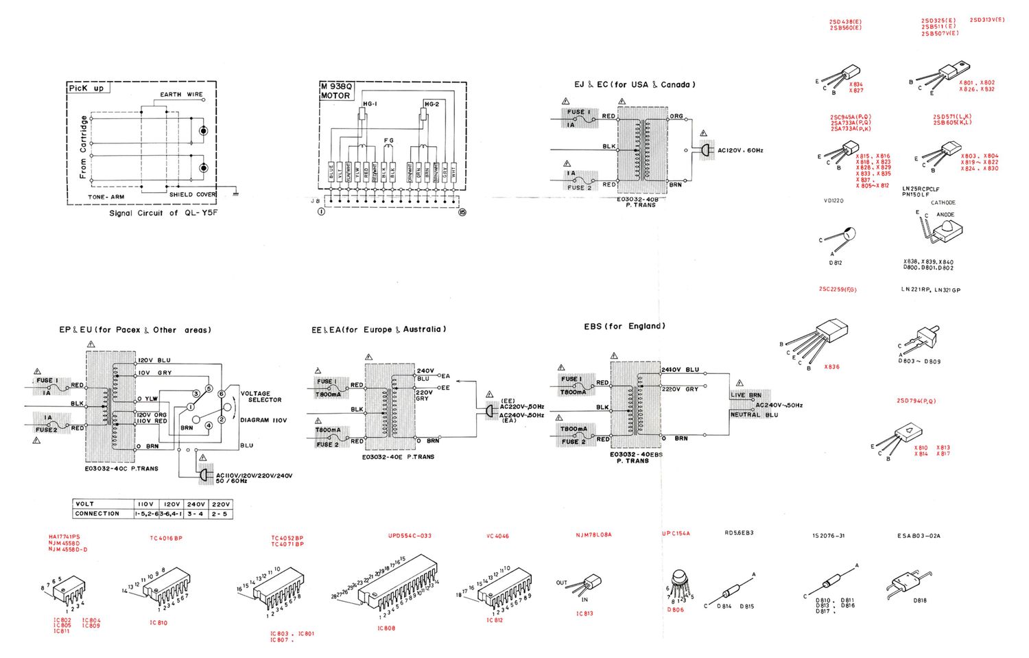
Jvc QLY 5 F Schematic
This is the 2 pages manual for Jvc QLY 5 F Schematic.
Read or download the pdf for free. If you want to contribute, please upload pdfs to audioservicemanuals.wetransfer.com.
Extracted text from Jvc QLY 5 F Schematic (Ocr-read)
Page 2
11. QL-Y5F Schematic Diaram
A B C D E F
2507941R0) PB
15 X81051 f-L:
L C846 l
PS @ a N- 1
1 -' /X811 1 4:
.. _ -_ 2$A733A [711711 1 1o,
__M,£~7K_1. (90> £5.31 . g 051
M5714 : 06:
1 7
0 250791. rm Ki 4'7 F 1
! (ea) 1 3;:
'i'K/fa. [551 2507941120) . 1 3|:
*1 0" 733A
5 1118061 1 0'3}
¢ ? . l 0141
~ F3 @ l - i ii I as:
E: E 1.?_-E . :3 LJ d zoms
151 u | H.
RBGO *- .;1 x 8 /
_ 18K - .- g o' I ~ 1
- 1. _ - .-.*+1"2 M _ H -m- -- ., -- #4 m ---__. g ,__. r .21.--- ,,
l 1 - 1 '
-1 ' same) 1:83;; //| a
' l-
T Ram l°( -1
R806 7" C9" 7 225 I
1.11
W3 1P..10 (9-41 '
. l . 1. C817
2 1 I? 3-9 @-"l R33: 8.2K 7 i
_ fi] eoaosz-u. , ' M, 2 _ E l
1'1 ,- vesoz. , ; 1191.11 2K .ceao 0.01 '
iceozh '0 1 l» . . a. , I
. 5 l .
LIL__§_?-:| C803 33 l\_ r- R839 03 f LRB'DR871 +5 - l; 4' I C835- I
R8 33K 0 . mnpsov 1C 803 E azx a: 32 8.2K r L7u/16V . 3, (28490.01 .822 0-1 I
011» l R' 233K 8 ¢ .4511 E -S #52819 Im/16V 21 '+ B; 41 R9326 R223 -Cl
1 v _ F A .1
C802 11>. 7 0'2 fl 367 1 x324 + X 83 2505711L Kimmy T 1" t, |
- Ram20K R840 rm 31331 42,111 > 22598; 5 R9041... eelw "1
* Fa 8-2 ___II1 l . . 21' (KL) 903 ' I K . El
. EIL¢ If s g . 1190. 3 _
75-1 8 so 4 ¢ ease ' r: 1 , M82. W a W , vnsov
. + r: L..___l [ 0 1470K A KNVQOS 33 R907 w 3.31 R93410K 47K
1 .9; M. 1-1 s L -, u.1 1.8K . 5, R909 1.8K aw ,
3 o 50 ¢ ¢ 17-71 1 V E w 110 x
' m a ¢_l L331 (:3 0811. m 31 0°01 335 E C83'o.022
1 ' 31-1 _. F57 at .x x l , :3 258560 CW'E 5'3 3 m a» 48} 1:31 A,
. 1 i M,
m 4 j 175'] ¢ 2 x :1 N «g \ (E) g 8 5 § *5 R94 SM 9 1C 812 C840 33p
4 A g 3 1 Y 5 :fx 3' °° Q 1~x:v . r , 80.5364; 2 17 ' li--1r
I °° N NN m 11. 15 m .05 .9 , a _ SA? x323 I815 X833 V .c § R91.
r-fi r1 I! .- A to? x, a: a: H in . h .. 1 _- -- $ W . 16+ 3p
5 4' 3 GI 33 53' lglcmsomfit'lceba l Laf ' -, i " 47 F/ v ' - ' ME" 0 '-"
I R2271 1C804¢E§1 1&0 cr 1:: a: I 001 i I A -' t g} 25 J 50 0325 -- m WEI-+1. 1
3 - [6-214 6 4 4.1%? . ' 3
W 1 000.53
217 51 fl :1. 28 s *
' a [ HI l 000 i
1 -Q $ : +
o 1c609¢ 829 :2
, 17/3511 1
X803 2505171) © 4 e (000 z * E :
K TP-l. EFT? 59 x L 9 1o 40 £93 1K {'3'
*- , _____ 9 - 11942
W . I . . .1. ~11 . 91
. °Jn NP33u 7
E. [- x E '
'7 804 11 MEI °
3 253505/ 1..M .1 __EL¢1C310 {a " / I
I R879 R88 0 ' 3? c345 |
: +5v 4 100ka 279'; 1 as / tin/16V 112.. 1 2 i
1111 (10047 MSW CH / 1% I
l gadgemfj 22K -
I 2.0 g 3813 I
| E" Maggi-1 <7 __I
l 1 2 3/; m m2. '3 ----------
| | > R812 1.311 m 3 I >
m 2
I R813 2.4K csoemu 3 N | ~.
I ' U 1 .
Mq% ~ I JV]
4 I I C5 . 1 I 101115 4
i [C 805 R815 19%; i I . AOmS
I uPC154A 19-1 47 R
l M6 _ .
IrJ pt 0, o kl 1"
1 1
l_ i swv REPEAT STAND avl
A B ' C D ' F
Notes: 6. When replacing the parts in the darkened area ( ) and 35:2;
1. Voltage values in are positive. those marked with A , be sure to use the designated parts
2. Voltage values in D are negative. to ensure safety.
3. indicates positive B power supply. 7. Parts in red indicate transistors or I05.
4. indicates negative 8 power supply. 8. This is the standard circuit diagram,
5. indicates signal path. The design and contents are subject to change without
notice.
_22_