Jvc QLY 3 F Service Manual

This is the 24 pages manual for Jvc QLY 3 F Service Manual.
Read or download the pdf for free. If you want to contribute, please upload pdfs to audioservicemanuals.wetransfer.com.

Page: 1 / 24
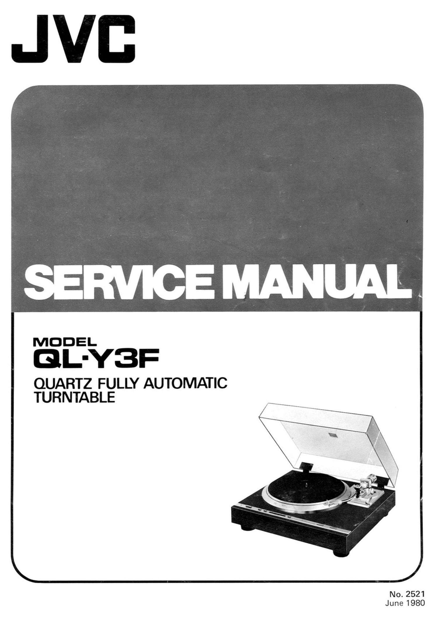
Jvc QLY 3 F Service Manual

Extracted text from Jvc QLY 3 F Service Manual (Ocr-read)


Page 2

Contents

Page
1. Specifications ............................ 1
2. Service Precautions ........................ 2
3. Names of Their Functions .................... 2
4. New Technology .......................... 3
5. Adjustment Procedures ...................... 4
6. Disassembly ............................. 5
7. Troubleshooting Charts ..................... 7

1 .Specifications

MOTOR SECTION
Motor

Drive system
Speeds
Wow and flutter

Signal-to-noise ratio
Speed detection
Starting torque
Speed deviation
Load characteristics

Drift

Power characteristics
Temperature
characteristics

Platter

TONEARM SECTION
Type

Effective length
Overhang

Weight range

Variable tonearm height
range

: Coreless, DC type, FG servo-

motor

: Direct drive
: 33-1/3, 45 rpm
: 0.025% (WRMS)

0.015% (by K & K measuring
method)

: More than 78dB (DIN-B)

: Frequency generator

: 650 g-cm

: Within 0.002%

: 0% (with 1309 total tracking

force)

I 0.0001%/H
: 0% (tIOV)

: 0.00005%/°c
: 31 cm

: Electronic servo controlled arm
: 245mm

: 15mm

: 14 - 19.5 9 (including headshell

weight)

: 42 - 48mm (preset to 45mm)

8. Connections Diagram ..................... 14
9. Exploded Views and Parts List ............... 15
10. TXX-278 Printed Circuit Board Ass'y and Parts List. 18
1 1. Packing Materials and Part Numbers ........... 21
12. OL-Y3F Schematic Diagram ................ 22
13. Accessories List ......................... 24
14. Parts List with Specified Numbers for
Designated Areas ........................ 24
Warning:

When replacing the parts marked with A , be sure to use
the designated parts to ensure safety.

CARTRIDGE SECTION

(Except for U.S.A., Candada and the U.K.)

Model

Type

Frequency response
Output

Channel separation

Load resistance
Compliance

Stylus tip

Stylus

Optimum tracking force
GENERAL

Power source

Power consumption
Dimensions

space such as a rack, etc.)
Weight

Accessory

.Z-1EB

: Moving Magnet (MM)

: 10Hz - 25,000Hz

: 3mV (1,000Hz)

: 25dB (1,000Hz) (test record

TRS-I)

: 47k52 - IOOkQ
: 10 x 10'6cm/dyne (Dynamic)

30 x 106cm/dyne (Static)

: 0.3 x 0.7 mil diamond
: UT-ZlEB
: 1.75 .+_ 0.25 g

: Refer to Table at page 24
: 16.9(H) x 48(W) x 43(D)cm

(6-5/8" x 1-15/16 x 1-3/4")
(Since the dimensions show only
the design measurements,
consideration is required when
installing the unit in a limited

: 9.5kg (20.9 lbs)

(without corrugated card board
case)

: EP adaptor ............. 1

Design and specifications subject to change without notice.

CHECKING YOUR LINE VOLTAGE (For U.S. Military Market and Other Countries)
Before inserting the power plug, please check this setting to see that it corresponds with the line voltage in your area. If
it doesn't, be sure to adjust the voltage selector switch to the proper setting before operating this equipment. The
voltage selector switch is located either on the set's or the chassis. Simply insert a screw driver into the voltage selector
switch and turn it in either direction while pressing slightly and in such a way that desired voltage marked on the switch
is positioned at the arrow marked on the rear panel or the chassis. The voltage selector switch accommodates up to
three turns in either direction.

No. 2521