Jvc QLA 75 Service Manual

This is the 34 pages manual for Jvc QLA 75 Service Manual.
Read or download the pdf for free. If you want to contribute, please upload pdfs to audioservicemanuals.wetransfer.com.

Page: 1 / 34
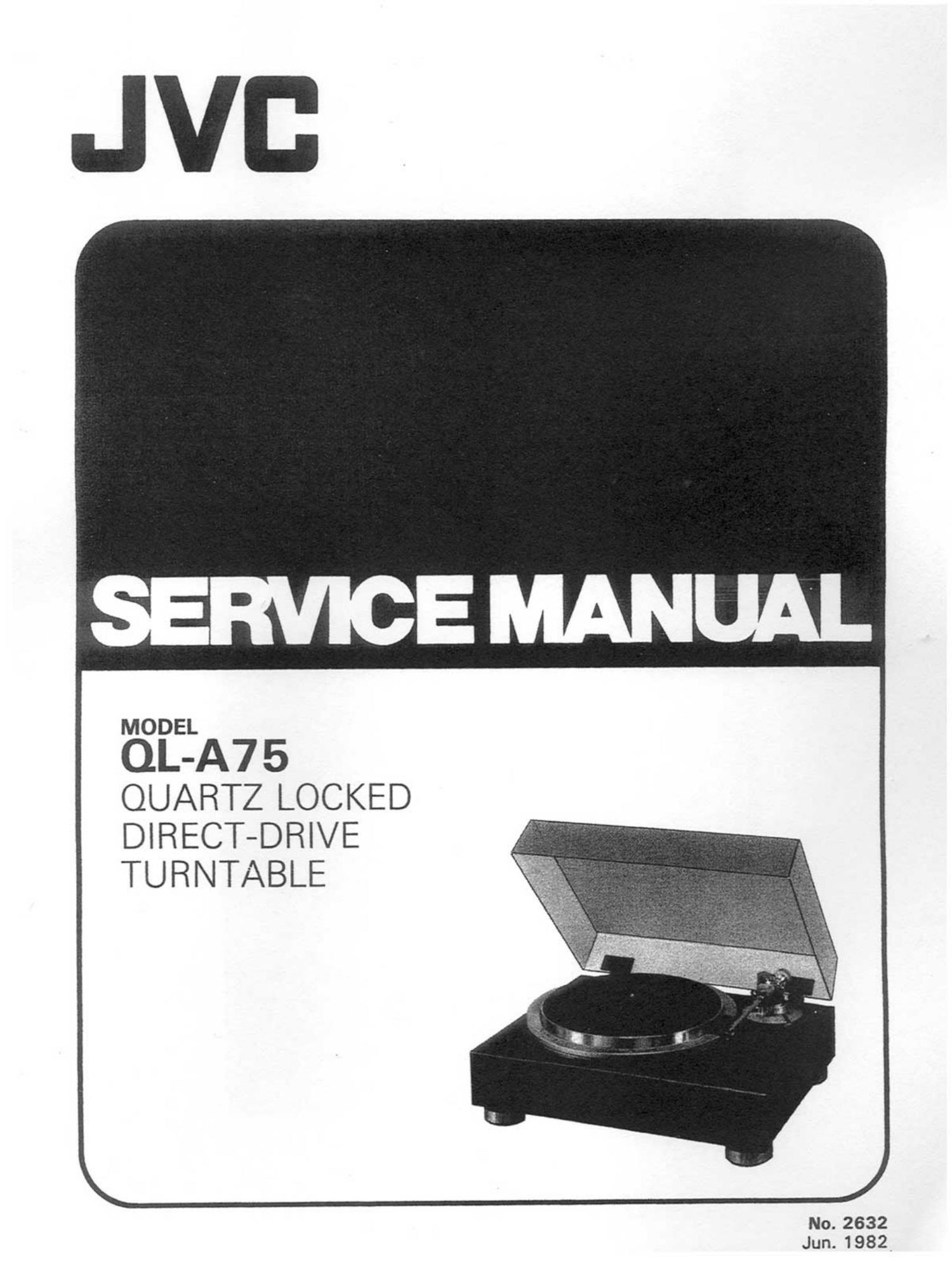
Jvc QLA 75 Service Manual

Extracted text from Jvc QLA 75 Service Manual (Ocr-read)


Page 2

Contents

Page Page
Features ............................................................... 1 1 0_ Connection Diagram ,,,,,,,,,,,,,,,,,,,,,,,,,,,,,,,,,,,,,,,,, 1 4
1 . Specifications ------------------------------------------------- 1 1 1. Exploded Views and Part Numbers ...................... 1 5
2. Service Precautions .......................................... 2 1 1 -( 1) Platter and Cabinet ................................. l 5
3. Main Parts Locations ........................................ 2 1 1 -(2) Tonearm .............................................. 1 5
4. Removal Procedures ......................................... 3 1 1 -(3) Mechanism Base .................................... 1 5
4-11) Removal of Tonearm Base Unit ------------------- 3 1 2. Printed Circuit Board Ass'y and Parts List ............. 1 7
4~(2) Disassemblage of Toneann Base Unit .......... 4 1 2-11) MDCo955A Motor Drive
5. Adjustment Procedures .................................... 4 p,c, Board Ass'y ,,,,,,,,,,,,,,,,,,,,,,,,,,,,,,,,,,,, 1 7
5-) Tonearm Height Adjustment ...................... 4 1 2-12) TXX-375Cl Main Amplifier, Power
5-(2) Tonearm Elevator Height Adjustment .......... 5 Supply & Control P.C. Board Ass'y ,,,,,,,,,,,, 19
5-(3) overhang Adjustment ------------------------------- 5 l 3. Packing Materials and Part Numbers .................... 2 1
SM) Tracking Force Adjustment ------------------------ 5 1 4. Accessories List .............................................. 2 1
5-6) Anti-Skating Adjustment --------------------------- 6 1 5. Schematic Diagram .......................................... 22
5-(6) AUtOUP POSitiOH Adjustment --------------------- 6 1 6. Power Cord Connections in Different Areas .......... 24
5-) Motor phase adjustment ---------------------------- 7 How to Handle the solderless Connector .............. 24
6. Block Diagram ................................................. 7 17, Parts List with Specified Numbers
7. Repair of Tonearrn Elevator ................................ 8 for Designated Areas ............................ Back Cover
8. Cleaning and Repairing the Cabinet ..................... 8
9. Troubleshooting .............................................. 9
9-(1) When Tonearm Action is Abnormal ............. 9
9-(2) When Turntable Operation is Abnormal ........ 10
CHECKING YOUR LINE VOLTAGE (For us. Military Market and Other Countries)
Before inserting the power plug, please check this setting to see that it corresponds with the line voltage in 6
your area. If it doesn't, be sure to adjust the voltage selector switch to the proper setting before operating this wv
equipment. The voltage selector switch is located undernearth the platter on the cabinet. 13:22:;
CAUTION Before selecting the Voltage selector swtich" to proper voltage disconnect the power plug. m

Features

A no-contact velocity detection system automatically lifts the tonearm and stops
the platter at the end of play.

0 Double-Servo Quartz control for absolute speed con-
stancy.

0 Dynamic 0 Damping System for Toneram new way to
end arm resonance and reduce coloration and inter-
modulation.

1.

Specifications

MOTOR SECTION

Motor : Coreless. DC Type
Drive System : Directhrive
Speeds : 33-1/3. 45 rpm

Speed Detection

System

Servo System

Start-up Characteristics
Wow and flutter

Signal-to-Noise Ratio
Starting Torque
Speed Deviation
Load Characteristics

Drift (hour)

-A75
2632

: Integrated Frequency Generator
: Double-Servo Quartz
: 1/4 rotation (33-1/3 rpm)
: 0.018% (WRMS)
0.03% (DIN)
0.008% (RMS) measured
by PG method
: More than 80 d8 (DIN-B)
: 1.8 kg-cm
: Within 0.0015%
: 0% (with 250 9 total
tracking force)
: 0.0001 %lh

Tapered, low-mass straight tonearm with New Gimbal

Support.

High-torque coreless DC servo motor and heavy platter
Luxurious mirror-finished, multi-Iayer solid cabinet.
High-output MC cartridge supplied (MC-200E).

PLATTER SECTION

Size

Weight (mat included)

: 308 mm die-cast aluminum
: 2.35 kg

TONEARM SECTION

Type

Effective length
Overhang
Height range

: Dynamic damping new
gimbal support tonearm
: 254 mm
: 15 mm
: 48-54 mm (preset to 51 mm)

Adaptable cartridge

weight range

: 4-17 9 (Straight arm pipe)
: *8-20 9 (S-shaped arm pipe)
: *16-34.5 (S-shaped arm pipe
using SW-A75)
Including headshell weight