Jvc QLA 7 Service Manual

This is the 36 pages manual for Jvc QLA 7 Service Manual.
Read or download the pdf for free. If you want to contribute, please upload pdfs to audioservicemanuals.wetransfer.com.

Page: 1 / 36
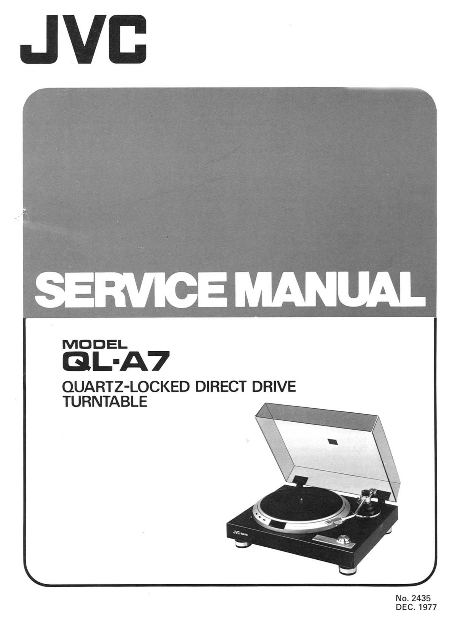
Jvc QLA 7 Service Manual

Extracted text from Jvc QLA 7 Service Manual (Ocr-read)


Page 2

Contents

Page
1. Specifications ........................................................ 2
2. Features ............................................................ 3
3. Service Precautions ..................................................... 3
4. How to Operate" (Names & Functions) ....................................... 4
5. Block Diagrams
5-(1) Servo (Motor) Control System ...................................... 4
5-(2) |C802 8i lC803 ................................................ 5
6. Troubleshooting
6-(1) Platter does not rotate ............................................ 6
6-(2) Platter rotates at a high speed ....................................... 7
6-(3) Rotation is not locked to the crystal oscillator frequency ..................... 7
6-(4) When the tonearm lifter lowering speed is exceedingly high ................... 8
7. Adjustment Procedures
Servomotor Section
7-(1) Power Supply Voltage Check .' ...................................... 9
7-(2) Lock Adjustment ............................................... 9
7-(3) Balance Adjustment of Drive Circuit .................................. 9
7-(4) Brake Mechanism Adjustment ....................................... 10
Tonearm Section
7-(5) Tonearm Height Adjustment ........................................ 11
7-(6) Tonearm Lifter Height Adjustment ................................... 11
7-(7) Overhang Adjustment ............................................ 11
7-(8) Headshell Angle Adjustment ........................................ 11
7-(9) Tracking Force Adjustment ........................................ 12
7-(10) Anti-skating Adjustment .......................................... 12
7-(11) Automatic Arm-lifting Position Adjustment .............................. 12
7-(12) Release Adjustment ............................................. 13
8. Parts Replacement
8-(1) Cartridge ..................................................... 14
8-(2) Voltage Setting ................................................ 14
9. Lubrication .......................................................... 15
10. Exploded Views and Parts List
10-(1) Turntable Baseboard (Cabinet) Assy .................................. 15
10-(2) Servomotor Assy ............................................... 17
10-(3) Tonearm Ass'y ................................................. 19
11. Connection Diagram of TXX-38 P.C. Board Ass'y ................................. 21
12. Printed Circuit Board Ass'y and Parts List
12-(1) TXX-38B (or C) Servo Control P.C. Board Ass'y .......................... 22
12(2) TSC-80A (to E) Power Supply P.C. Board Ass'y .......................... 27
12(3) TXX-120A Auto Mechanism Control P.C. Board Ass'y ...................... 28
13. Packing Materials and Part Numbers .......................................... 29
14 Accessories List ....................................................... 29
15. QL-A7 Schematic Diagram ................................................ 30
16. Parts List with Specified Numbers for Designated Areas ............................. 32

Warning: .
When replacing the parts marked with A. , be sure to use the designated parts to ensure safety.